
Laser Stars Revisited
During some time off, I decided to rewrite the laser_stars (http://www.robopenguins.com/laser-stars/) code using the ROS framework. During the original project I ended up creating a lot of the configuration / diagnostics / reconfigurability that you’d get for free in ROS. It’s not a perfect fit since ROS is focused on robots, but I treated the laser point on the ceiling like a robot. The only library that seemed similar to what I wanted was http://wiki.ros.org/visp_auto_tracker . However, I think what I was doing was different enough that it didn’t make a good base for development.
I created the repo https://github.com/axlan/ros_scratch to capture my development. In it, I organized my project into 4 ROS packages.
ar_framer
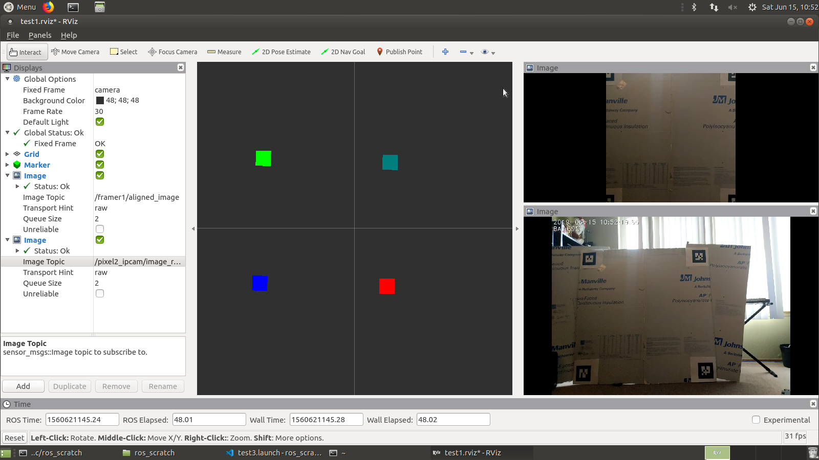
This package takes a camera feed, find the four corners of the target area and creates a new image output snapped to the target area with the perspective fixed.
The first thing I did was go over the basic tutorials and setup http://wiki.ros.org/ROS/Tutorials . I created a script to do the basic ROS install: https://github.com/axlan/desktop_setup/blob/master/install_ros.sh . From there I wanted to make sure I could grab images from a webcam. This turned out to be a lot harder then I was expecting. After having issues with http://wiki.ros.org/libuvc_camera (though I used the instructions from there to set up the Udev rules), I found http://wiki.ros.org/cv_camera which I was able to get working.
1
2
3
4
5
6
7
8
sudo apt-get install ros-melodic-cv-camera

rosparam set cv_camera/device_id 0
rosparam set cv_camera/image_height  600
rosparam set cv_camera/image_width 800
rosrun cv_camera cv_camera_node

rosrun rqt_image_view rqt_image_view
Now that I confirmed I could use the camera, I wanted to reproduce the QR code framing of the “canvas on the ceiling. After doing some searching I realized that http://wiki.ros.org/ar_track_alvar did exactly what I wanted and that AR tags were actually a better reference image then QR codes.
I just needed to install the package sudo apt-get install ros-melodic-ar-track-alvar
Instead of going straight to tracking with a camera, I made a roslaunch that would test the tracking using a test image https://github.com/axlan/ros_scratch/blob/master/src/ar_framer/launch/test1.launch . I used an image_publisher node as the fake camera. I also realized I needed a reference frame for the AR tracker. Basically this defines the coordinate system it’s using. It took a little trial and error with the transform tool http://wiki.ros.org/tf2 and the tools from the tutorials that let you inspect topics and nodes.
This worked great for static images, but I hit another set of problems when I tried to do this in real time with a 720p USB webcam. First, the camera control node had problems using the full resolution. After fighting with it for awhile I moved to using an IP webcam server running from my phone.
I switched to using the video_stream_opencv package for the camera (see https://github.com/axlan/ros_scratch/blob/master/src/ar_framer/launch/test3.launch ) I tried https://play.google.com/store/apps/details?id=com.pas.webcam&hl=en_US which would occasionally crash and had a huge latency. I thought I might have better luck with a server that supported RTSP and used https://play.google.com/store/apps/details?id=com.shenyaocn.android.WebCam. This wasn’t much better, but seemed a little more stable. This was mostly down to the camera drivers and seems like it wouldn’t be an issue on an actual robotics platform with lower latency video.
I was able to get the tracking to work in real time an align the target frame, but it was pretty fragile. I would have to set up a lot of logic to try to get around the limitations.
This package fully works, but probably needs to have the reliability changes I mentioned added to be truly useful.
laser_pointer_tracker
Next I would work on the code to track the laser itself. I started with a fairly straight port of the original OpenCV code. I first started looking at rviz on how to build something similar to the calibration script to set the parameters for laser detection. Basic porting was pretty straightforward, but I decided to support dynamic configuration to make the UI as usable as possible.
To run the node using a static test image:
1
2
3
4
roslaunch laser_pointer_tracker test1.launch
rosrun rqt_gui rqt_gui -s reconfigure
rosrun rqt_image_view rqt_image_view /laser_pointer_tracker1/thresholded_combined &
rosrun rqt_image_view rqt_image_view /image_publisher1/image_raw &
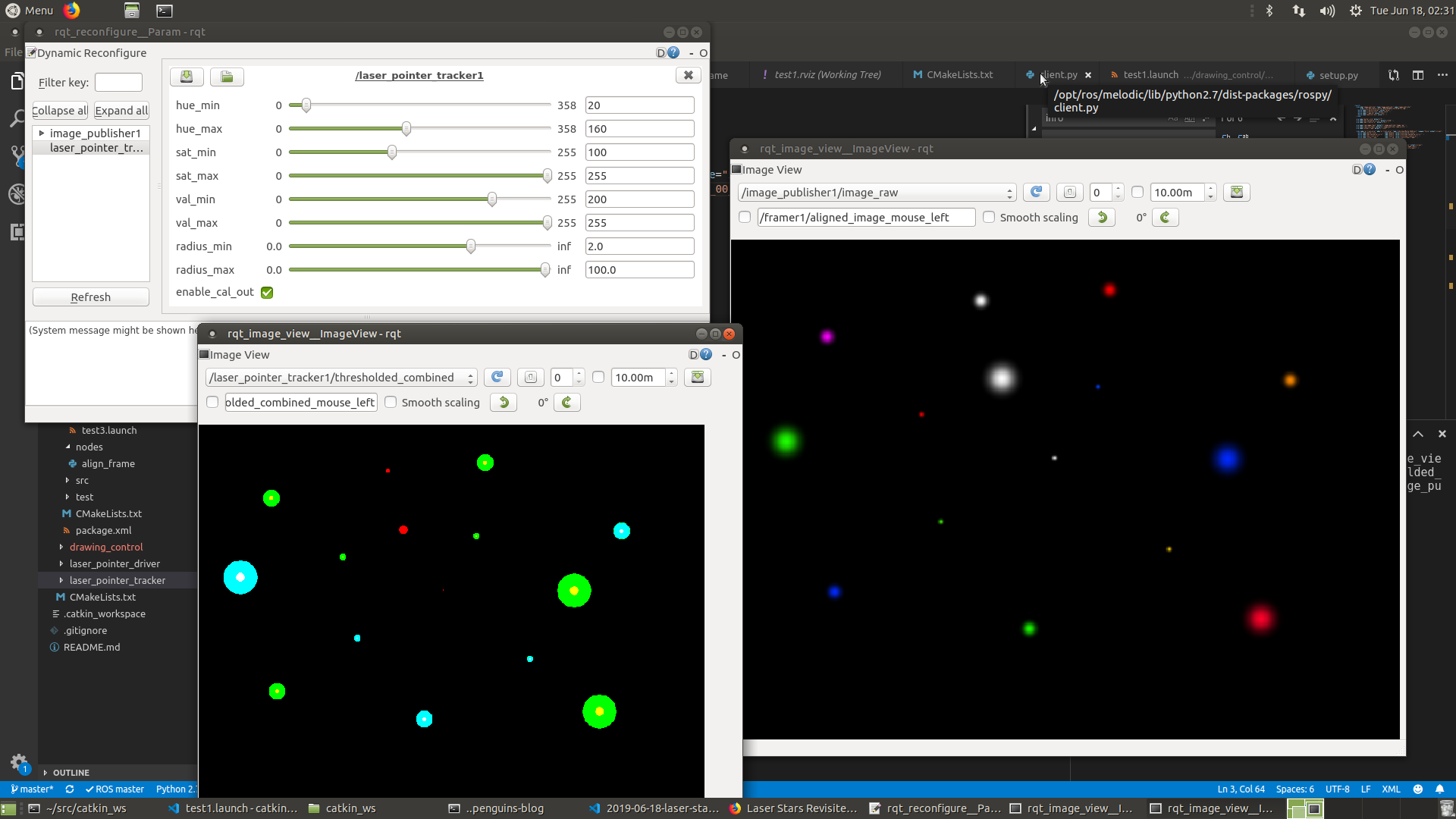
Initially I wanted to use rviz for displaying the output, but since things were 2D it seemed easier to just output images.
drawing_control
I started looking at the simulator packages to start testing controllers, but it seems that ROS has mostly coalesced on “realistic” simulations like using a real robot model in Gazebo. Followed http://wiki.ros.org/stage/Tutorials/SimulatingOneRobot but needed to use http://wiki.ros.org/teleop_twist_keyboard. However even this didn’t really add much value to the dummy simulator I had made.
Started writing a controller package. To actually separate the logic into multiple files, had to go into the ROS python packaging rabbit hole. http://www.artificialhumancompanions.com/structure-python-based-ros-package/ was a pretty good intro.
With the basic skeleton in place I started writing the actual controller. First I ported the code to take movement instructions and translate that into service calls for the turtlesim. To have it make more sense, I added a node to wrap the turtlesim to add error / smooth out behavioral differences with the laser.
Originally I was hoping I could directly reuse an existing ROS closed loop controller. Even something simple like a PID or Kalman filter. Once again though, I was hit with the issue that the ROS packages I found were very focused on “real” robots, so they mainly expected odometry, IMU, and the like. Since the movement of the laser was closer to “teleporting” then traditional robot movement, it seemed like just working to improve my original calibration code would be the better approach.
I started porting the calibration code and had to modify it to work without being able to wait for the position updates.
I ended up creating a node that would handle for service calls and take a file describing the set of laser movements. It would then facilitate sending these to the service that communicated with the laser. I also created a wrapper that would instead send these to a turtlesim node.
1
2
roslaunch drawing_control test1.launch
rosservice call /ctrl1_node1/draw_file /home/axlan/src/catkin_ws/src/drawing_control/movements/test_square2.mvs
However, since I didn’t fully flesh out this control system after I added the calibration, it is not currently in a working state.
laser_pointer_driver
The last package I worked on was the driver that would send the serial commands to the laser.
Got the serial connection to the Arduino working. Had to add permissions, probably use add to user to a group with the right permissions: sudo chmod 777 /dev/ttyACM0
I got the manual movement using keyboard teleop working. Next I tried to use a joystick. This sort of worked, but I need to do some sort of remapping, or use the buttons directly: sudo apt-get install ros-melodic-teleop-twist-joy sudo chmod a+rw /dev/input/js0
This all worked pretty well and it was nice to be able to isolate this configuration from the rest of the system and provide a more straight forward abstraction.
Conclusions
This project once again ended mostly as a failure. Running out of time to work on the project, I threw together a script that could at least translate image files to laser movements https://github.com/axlan/ros_scratch/blob/master/src/drawing_control/scripts/ctrl_dumb_image.py
I wanted to have a simpler setup then the ceiling to start, so I bought some foam and mounted the AR tags. To make the results less dependant on perfectly lining up the stars, I wanted to create a screen that would glow in the dark. I went through a lot of options from powder to make paint, to glow in the dark tape. They were all pretty expensive, and I ended up going with a vinyl sheet https://www.amazon.com/gp/product/B0778QQYBB/ref=ppx_yo_dt_b_asin_title_o01_s00?ie=UTF8&psc=1. This turned out to be a total waste of money since it would only glow for less then a second even after being held under the laser for extended periods.
Giving up on this, I tested using just the stars. Here you can see the system attempt to draw “HI”:
This worked OK, but I’d have to adjust the Arduino drivers to move more slowly to get a more consistent glow on the areas passed over.
All in all I was able to implement the project in ROS and fully take advantage of the framework, but once again was limited by the sensors, materials, and lack of time.