
Making a Turtle Bot 1: Hacking a Mint Cleaner
When my daughter showed interest in a turtle bot board game, I decided to try building my own turtle robot.
Turtle bots have been a thing in robotics and programming for decades. While Logo wasn’t something I grew up with, it was a lot of kids’ introduction.
We had been given a copy of https://boardgamegeek.com/boardgame/147370/robot-turtles when my daughter was born, and we gave it a run through. It held her attention for a bit, but (as the game acknowledges) it takes some parental sound effects and acting to add to the excitement. I thought remaking the game with a real robot that could be controlled by cards would be a fun project while also making the game more interesting.
Planning
Going into this project, I considered the following features:
- Differential drive - Two motors and controller to turn in place and move forward
- Dead reckoning - The robot could use wheel speed, accelerometer, and or gyro sensors to measure its own movements
- Absolute positioning
- Using onboard or external cameras and a system like AprilTag or Aruco markers
- Light sensor on patterned floor - I considered using an array of light sensors like those used for a line following robot to navigate a floor with marked tracks
- GPS - Since I’m already familiar with it, this would be the “easiest” solution. However, it would only work outside, and isn’t great for orientation
- Card reader - The interface for giving the robot instructions with cards
- User interface
- Status display for the game
- Cute face for the robot
- A GUI for controlling things
To implement these features, I had to consider what hardware would be involved. While some of the sensors could be added or removed without greatly affecting the overall architecture, I wanted to figure out the computers that would be involved upfront. Here are the options I considered:
- Onboard robot:
- Raspi
- Cellphone
- ESP32
- Offboard robot:
- Laptop
- Cellphone
I liked the idea of having a cellphone on the bot since it could be a face display, processor, and camera. However, I couldn’t find a lot of existing projects in this area, so it seemed like it would be a lot of work.
With all these options I decided that the easiest way to get started would be:
- Set up a differential drive robot
- Have some basic dead reckoning to be able to roughly perform the desired maneuvers
- Use an ESP32 onboard to do the low level motor driving
- Use a laptop for the GUI and high level control
- Use an NFC or RFID card reader connected to the laptop
I could probably get rough movements without absolute positioning. This would simplify the hardware I needed to sort out up front and avoid needing to “fuse” the sensor information between the dead reckoning and absolute positioning.
I did want to make it cute, but I realized it was much easier to just stick a stuffy over the top than worry about a digital face.

Building the Hardware
I’m not a skilled mechanist, so I have no interest in building a robot body from scratch. I considered going with a chassis kit, or even a whole robot kit. While I was looking, I remembered a friend had given me a broken robot vacuum years ago that I still had lying around.
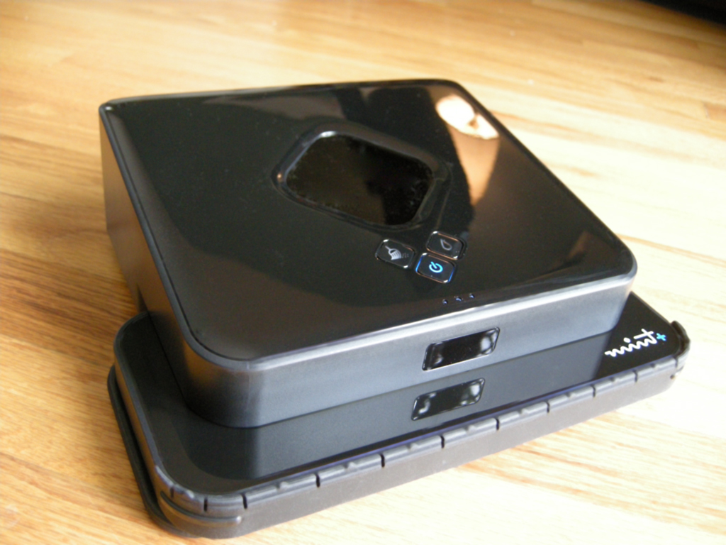
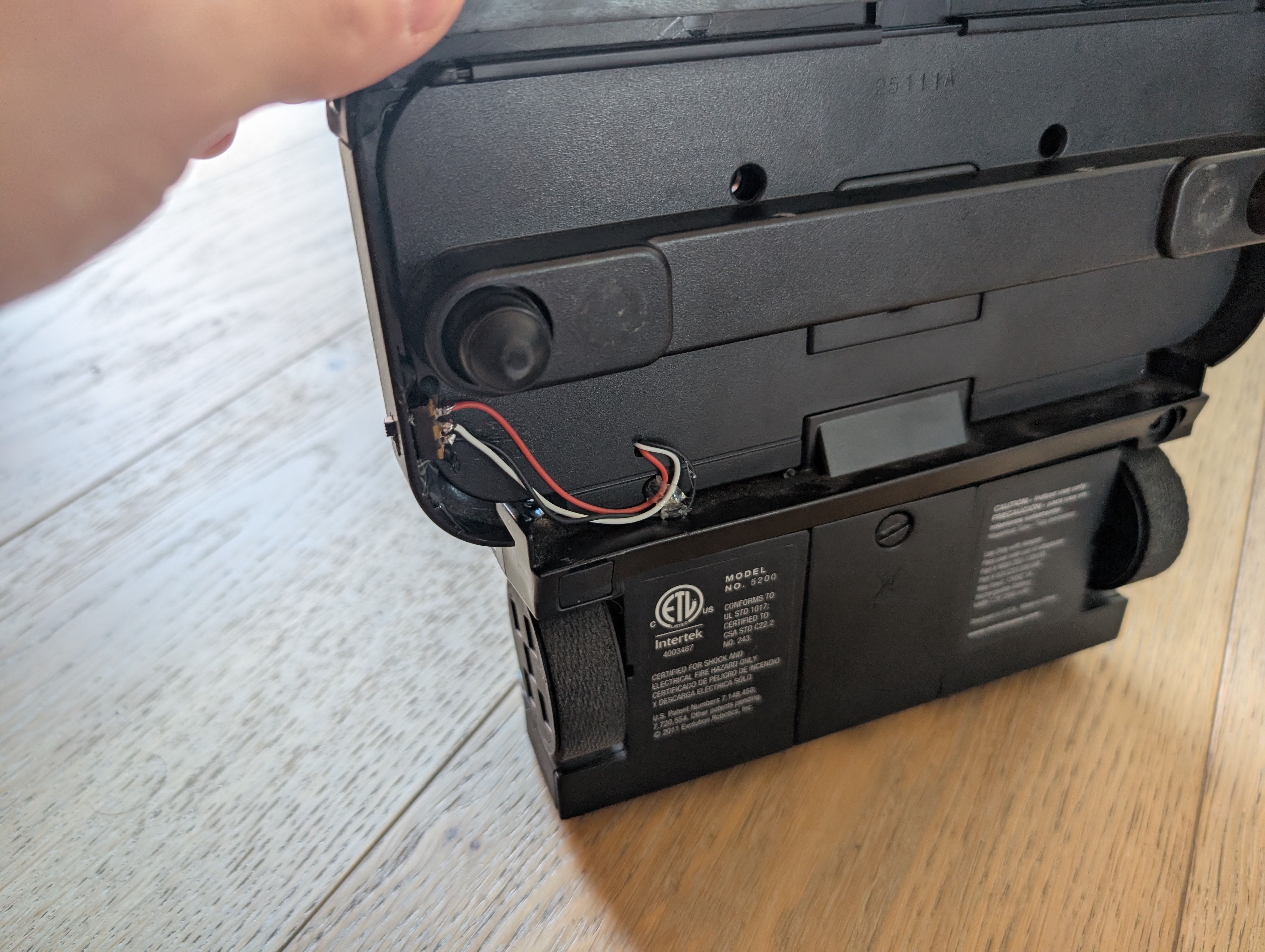
It was a Mint Plus 5200, and the only thing that seemed to be wrong with it was a dead battery. The battery was easy enough to buy, and I had a fully functional robot to start with.
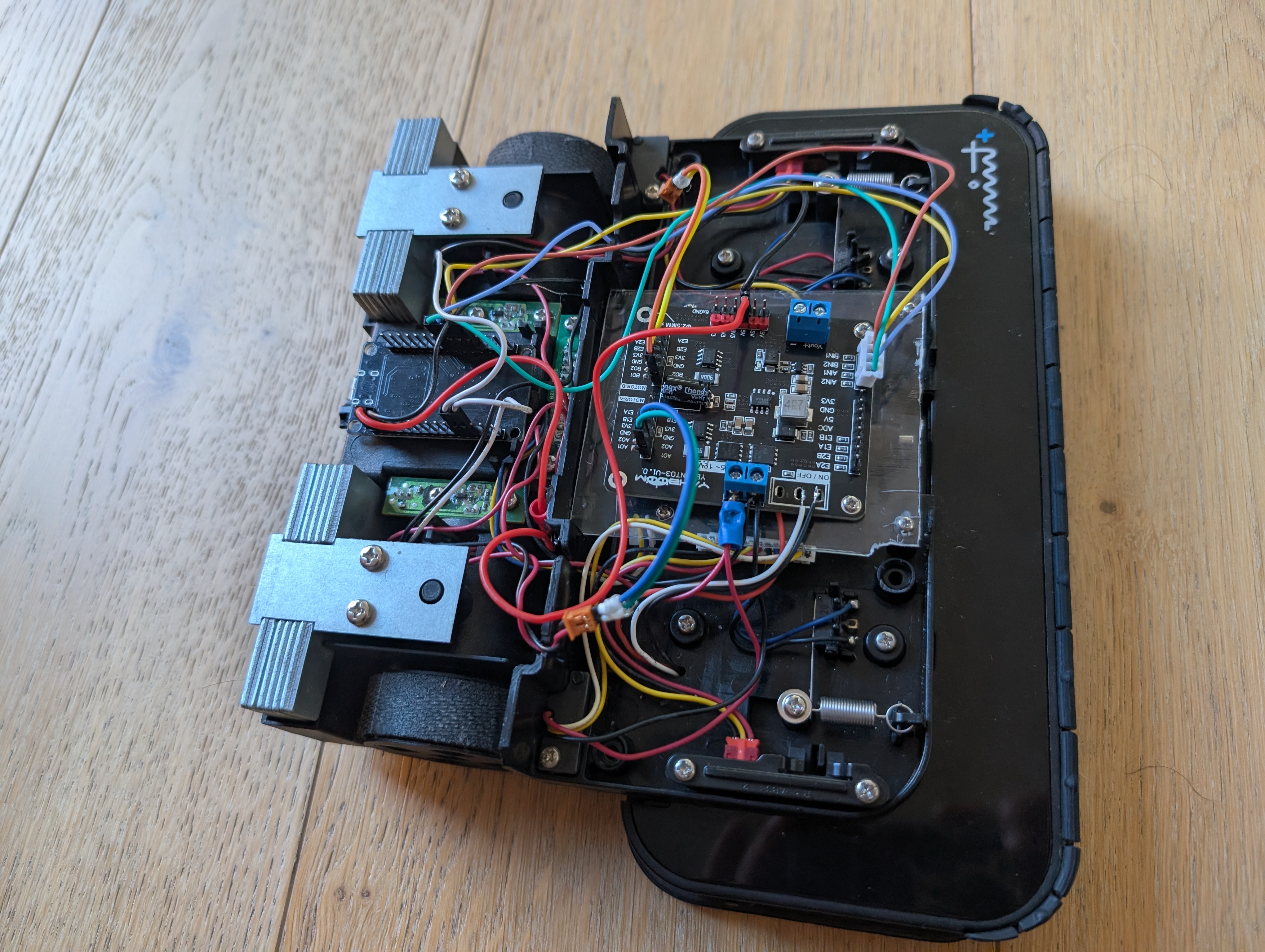
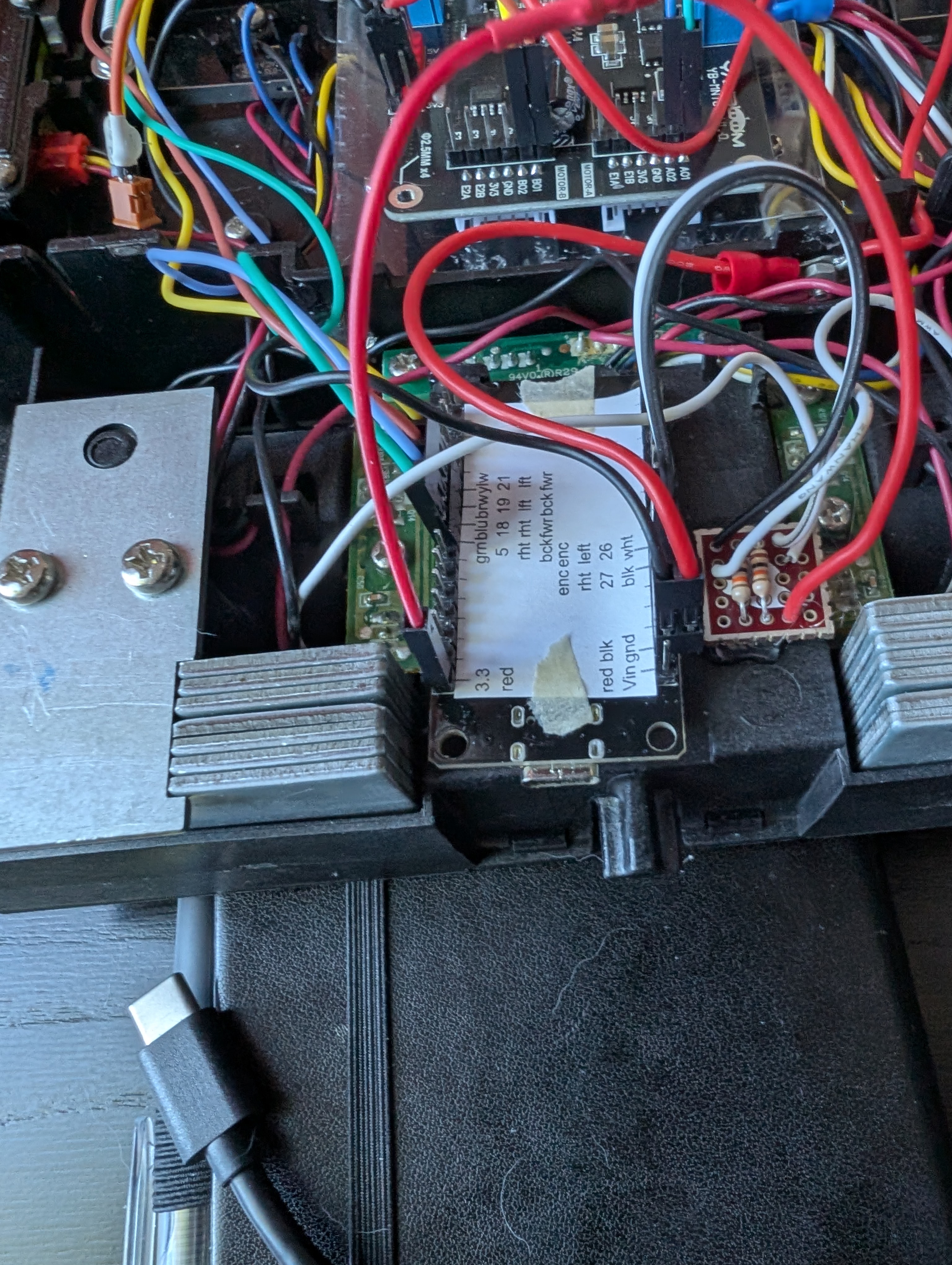
Opening it up, it was very helpfully labeled:
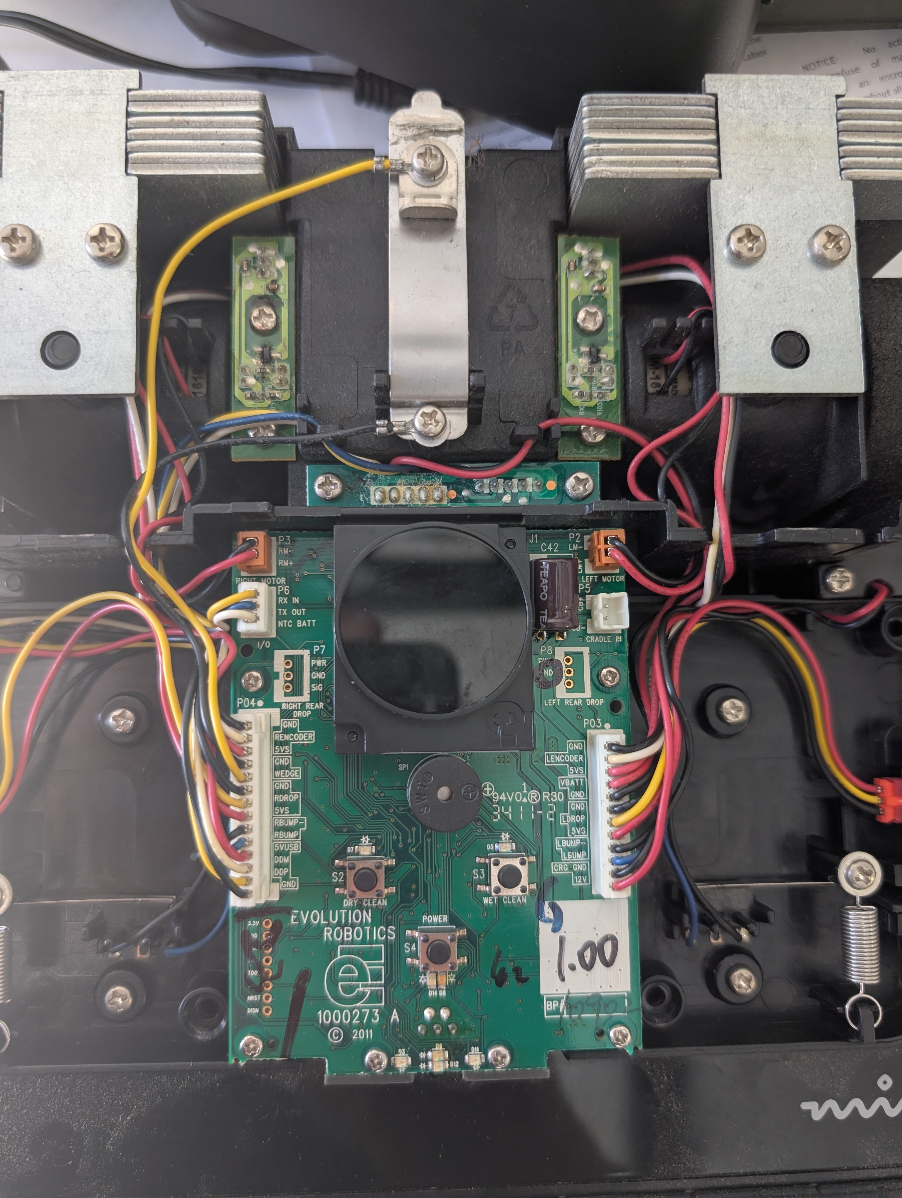
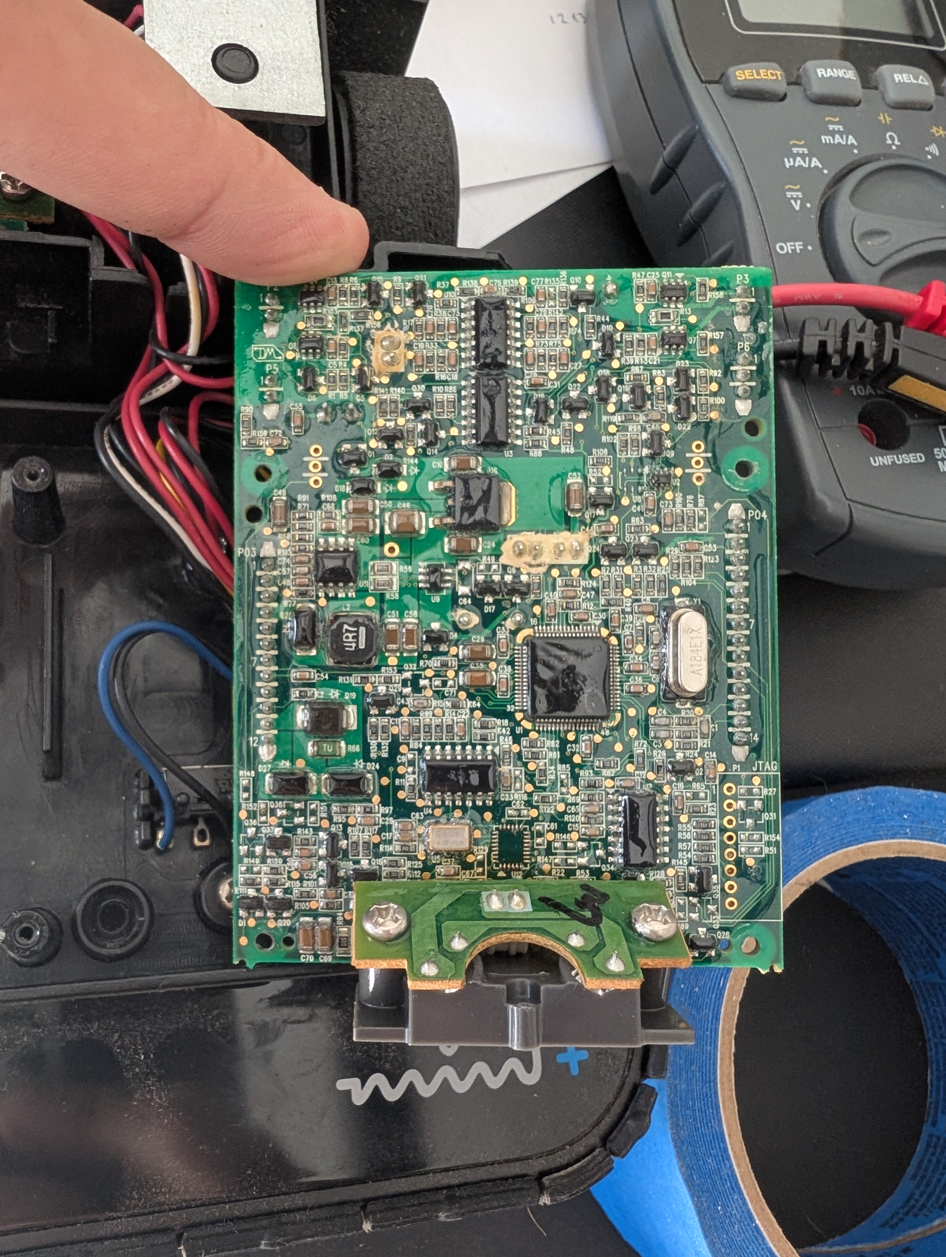
Unfortunately, the board was very dense, and covered in some sort of glue:
To “hack” this robot, I had 3 options:
- Reverse engineer the processor. This would let me potentially use all the sensors (including the huge absolute positioning module on top) and avoid needing any additional sensors.
- Reuse some of the components of the control board, but use my own processor. This might give me access to the voltage regulators, the motor controllers, and or some of the sensors.
- Replace the whole control board.
This was actually a fairly ripe target for reverse engineering. It has an Atmel chip, serial lines, and a JTAG connector. However, I wanted to take the path of least resistance. For basic motor control, it seemed easiest to just replace the whole control board. This left me with:
- The two “HN-27GM 1618T(R) DC-06V-250RPM” geared DC motors
- A 7.2V NiMH battery
- Wheel encoders for wheel speed measurement
- Bump / drop sensors
After a little searching, I decided that I’d use a 2-Channel Motor Drive Module https://category.yahboom.net/products/dual-md-module. This is a nice cheap breakout board for the AT8236 motor driver with some voltage regulators. I was mostly looking for something cheap and simple. It has two control pins for each motor. Feeding a PWM signal into one input or the other makes the motor spin forward or backward. Having both inputs high holds the motor in place acting like a break.
It was easy enough to set up and I quickly got a basic test working.
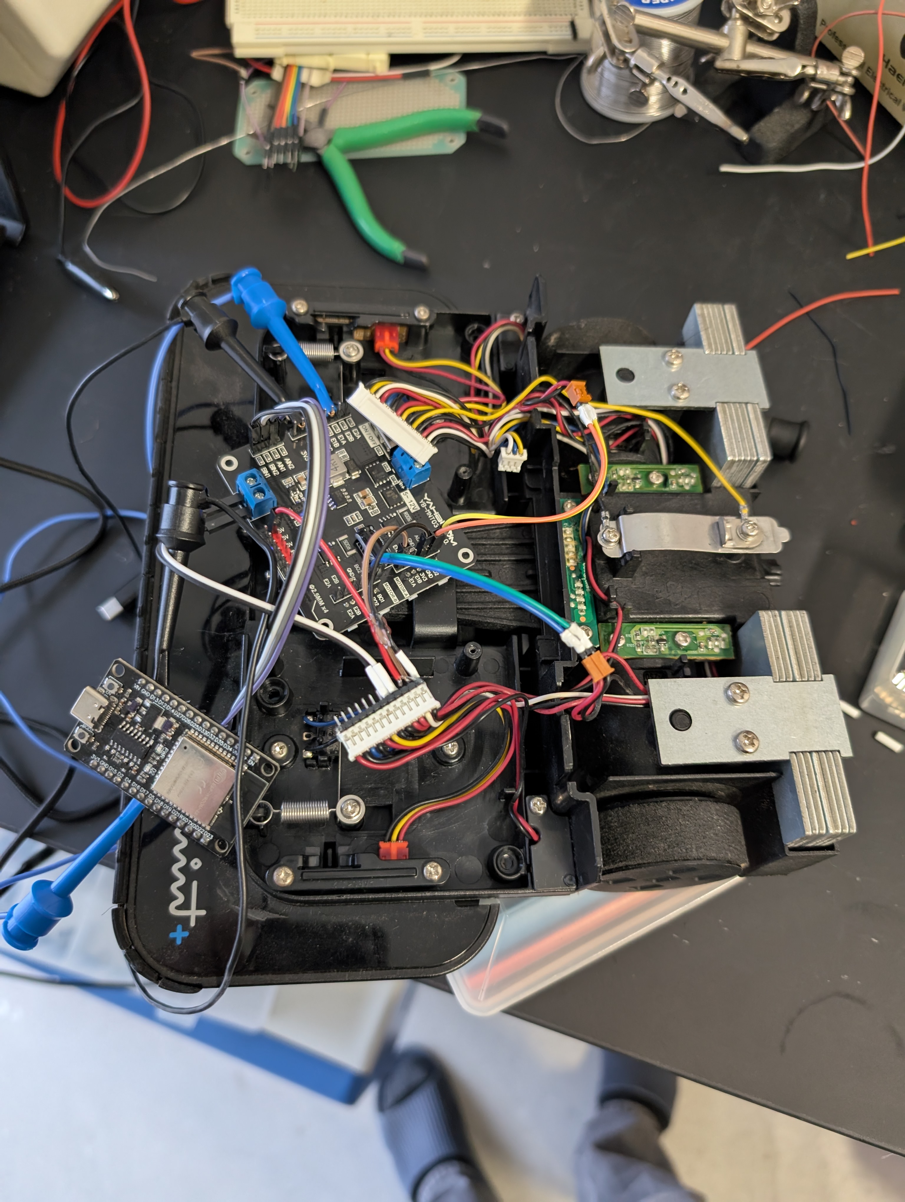
While I initially tried to use the board’s original connectors, I eventually recrimped the wires to try to make everything as solid as possible.
I also initially tried to fit everything in the original case. The motor control board was a bit too tall, so I started removing unnecessary connectors and shaving things down. Only part way into this process did I realize this was all pointless. It was around this point I decided I would cover everything with a stuffy. Since it was going to be covered anyway, I just cut a big hole in the top of the original plastic to make room for whatever I needed.
Since I had removed the charging circuitry, I decided to use an external charger for the battery (https://www.amazon.com/dp/B09F5J1XPP?ref=ppx_yo2ov_dt_b_fed_asin_title). I rewired the plug on the bottom to go directly to battery. Also, I moved the switch from the motor control board which controlled power for all remaining electronics from the board itself, to a cutout I made in the plastic with a dremel:
Encoder Debugging
I made plenty of silly mistakes as I was putting together the hardware. For example I shorted the motor controller with a loose wire and some of the GPIO pins I used initially interfered with the ESP32 boot. I did have one problem that required some real debugging though.
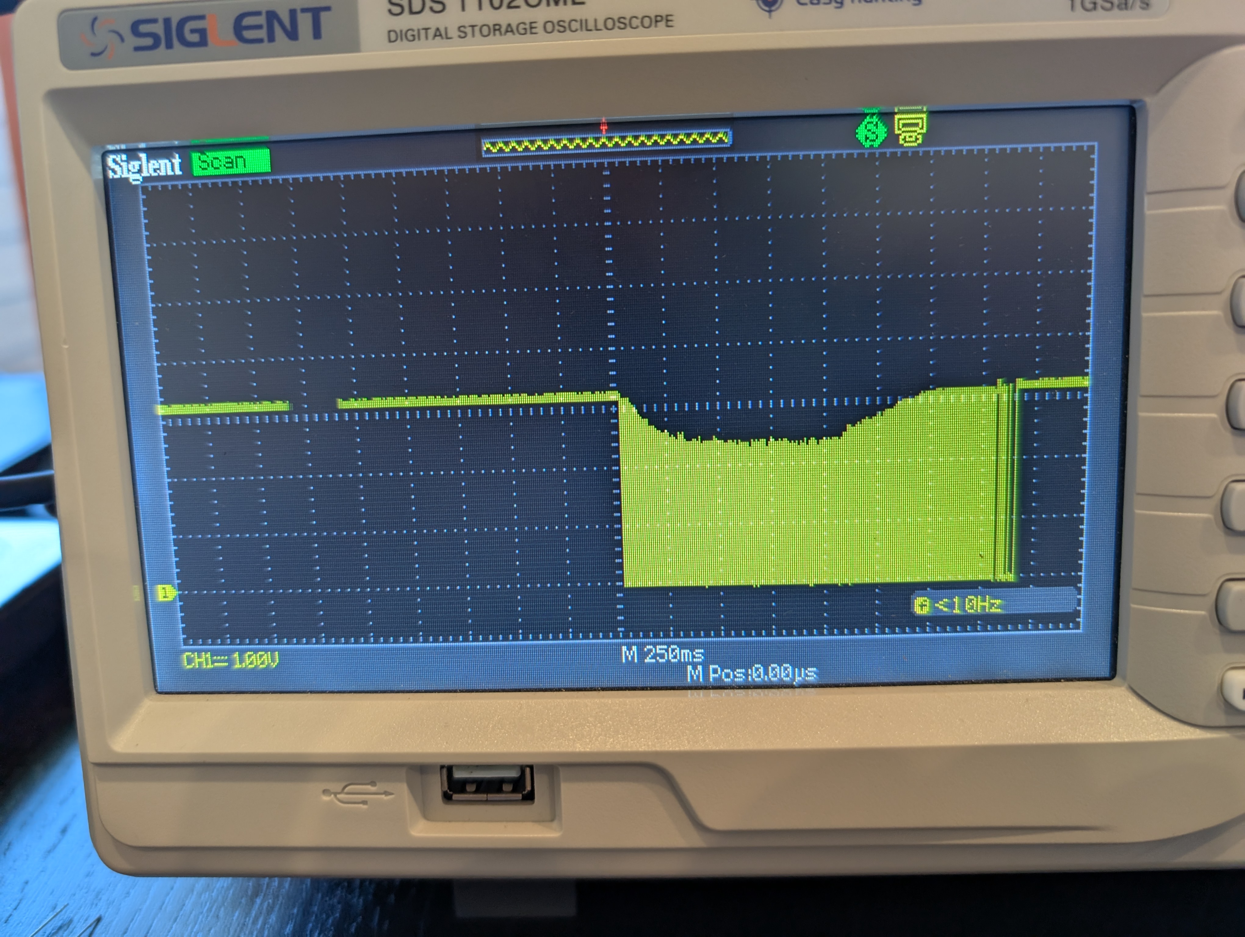
When I was initially testing the motor encoders, I noticed they needed a pull up resistor to work (they were open drain). This was fine, and didn’t even require any extra components since the ESP32 has built in pull ups. However, when I started trying to measure speed for real, I started getting totally incorrect results. When I looked at the results on an oscilloscope, I saw that the sensors worked fine at lower speeds, but at higher speeds they were not reaching the “high” voltage level:
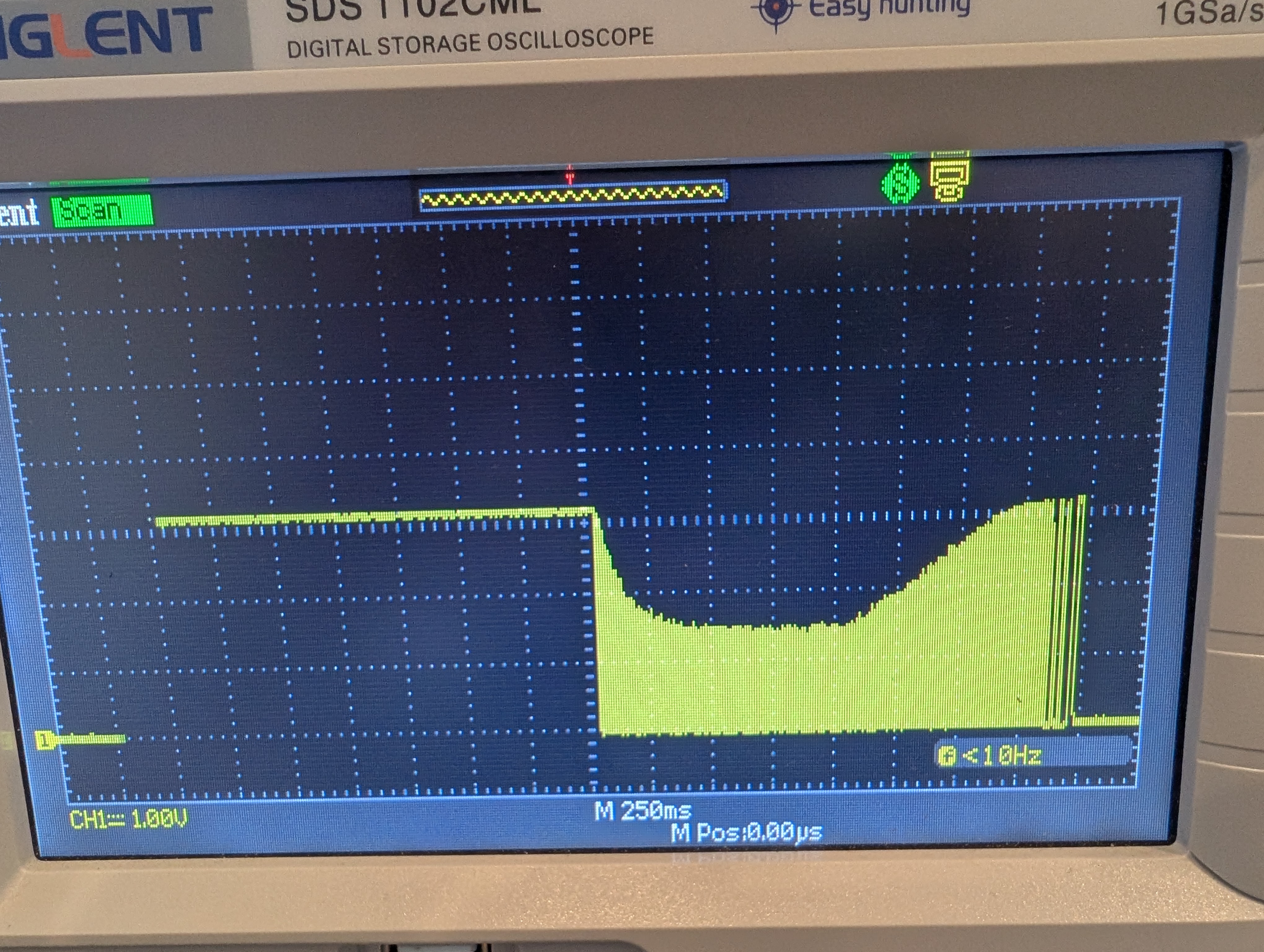
The scope shows the sensor outputting pulses that reach the expected 3.3V at low speeds, but only reaching about 1.5V when the wheel spins rapidly. I correctly guessed that the pull up resistor was too large, which wasn’t letting enough current to flow with whatever the effective capacitance of this system was. Going from a 30k (or whatever the ESP32 uses internally) to a 10k resistor fixed the issue:
However, this meant I had to add the external pull ups:
(you can see my original GPIO pin choices that used some pins interfering with boot up)
Software Development
Going into the software design for this project, I naively thought that there was probably going to be an “off the shelf” solution for a differential drive robot. This is a very basic project that people have been doing for decades.
I had initially planned on using ROS (a “robot operating system”) since it brings a lot of tools that simplify robotic development. However, as I was reminded as I worked my way through the tutorials, this comes with a lot of unnecessary complexity.
There are a lot of open source projects that are at varying levels of polish:
- https://medium.com/@jiayi.hoffman/ros-2-control-robot-control-the-right-way-d0e72e7f1b6c and https://articulatedrobotics.xyz/tutorials/mobile-robot/applications/ros2_control-real/ use an Arduino running https://github.com/hbrobotics/ros_arduino_bridge paired with the ROS node https://github.com/joshnewans/diffdrive_arduino/. The Arduino takes low level commands over the serial port for control.
- https://www.hackster.io/amal-shaji/differential-drive-robot-using-ros2-and-esp32-aae289 runs micro-ros on an ESP32 which is closer to what I wanted. I actually used this as a starting point, but found it fairly unpolished and with lots of mistakes.
- There is also https://github.com/purwar2016/DeadReckoning-library and the better maintained https://github.com/ArminJo/PWMMotorControl which provide self contained Arduino libraries for differential robots.
- Then there’s the official ROS turtle bot example https://ros2-industrial-workshop.readthedocs.io/en/latest/_source/navigation/ROS2-Turtlebot.html
As I dug into these, a constant issue was how inflexible and non-modular most of this code was. Using a slightly different encoder sensor or motor controller might require huge rewrites of the code to be supported. Many of the libraries were not written in a way that was easily portable between Arduino and ESP32. Using a framework like ROS or micro-ros, totally changed how the code needed to be structured.
The first thing I did was spend some time getting a handle on how micro-ros worked. I did a few sample projects, and eventually was able to get the features I needed working on my ESP32 so I could control the bot.
I initially adapted https://www.hackster.io/amal-shaji/differential-drive-robot-using-ros2-and-esp32-aae289 to work over UDP. When I started debugging, I decided I would need to do a pretty significant refactor to bring it up to my standards.
I rewrote the motor driver and encoder interfaces to implement a generic abstraction layer. I spent a good amount of time “getting this right” even though there are a bunch of other projects that do the same thing with more development time behind them. This is where I realized how hard these interfaces are to universally abstract, and how much of the design comes down to the set of use cases a person prioritized.
After finishing a full micro-ros implementation https://github.com/axlan/mint_ros_bot/blob/demo1/firmware/tests/micro_ros_vel_ctrl.cpp, I decided that for testing the controller basics, it would be better to start with a simpler framework and just get the low level controller working.
Using the same skeleton I’ve used for a few other projects, I made a new main application. It used the Arduino NetworkManager library to handle setting up the WiFi and server configuration, and it would take commands and report status over MQTT. This isn’t really that far from how ROS handles it, but this sheds some of the layers of complexity for the initial testing.
With the basic set up, I went ahead and tried to drive forward:
Not only did it not go straight, but my original estimates for the encoder parameters were way off and the distance calculations were way off from what I expected. At the very least I’d need to send different control signals to the motors to have them spin at the same speeds.
I reworked my firmware to accept more flexible commands: MANUAL,<LEFT PERCENT SPEED>,<RIGHT PERCENT SPEED>,<DISTANCE>,<ENCODER CHECK> , and I used trial and error to work out parameters that worked for the maneuvers I wanted. I used https://mqtt-explorer.com/ as an easy way to manually send MQTT commands. Once I had these down, I made a CLI for sending the commands and driving the bot around with the arrow keys teleop.py:
Next Steps
Now that I’ve gotten a handle on the basics, it’s a bit easier to see where I’d want to go with this. The simplest step would be to replace the current raw PWM signals to the motor with PID controlled speed requests. At the very least this should handle keeping the two motors in sync. To do this I’d want to set up a more robust communication interface to collect data.
In part two, I’ll explore whether speed control is sufficient to get accurate enough control for my silly toy and create the user interface using the cards.