Sad Pumpkin Failure
My failed attempt to make an IoT nightlight.
When my daughter got a cute nightlight, I thought it would quick project to add some IoT capabilities to turn it into a imitation Hatch light. The project ended up perfectly designed to string me along by its sunk cost. Don’t worry, her nightlight is safe, I got a second to take apart.
Good Start
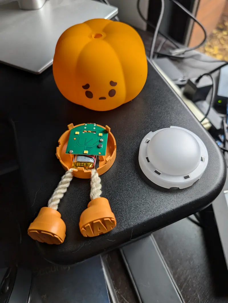
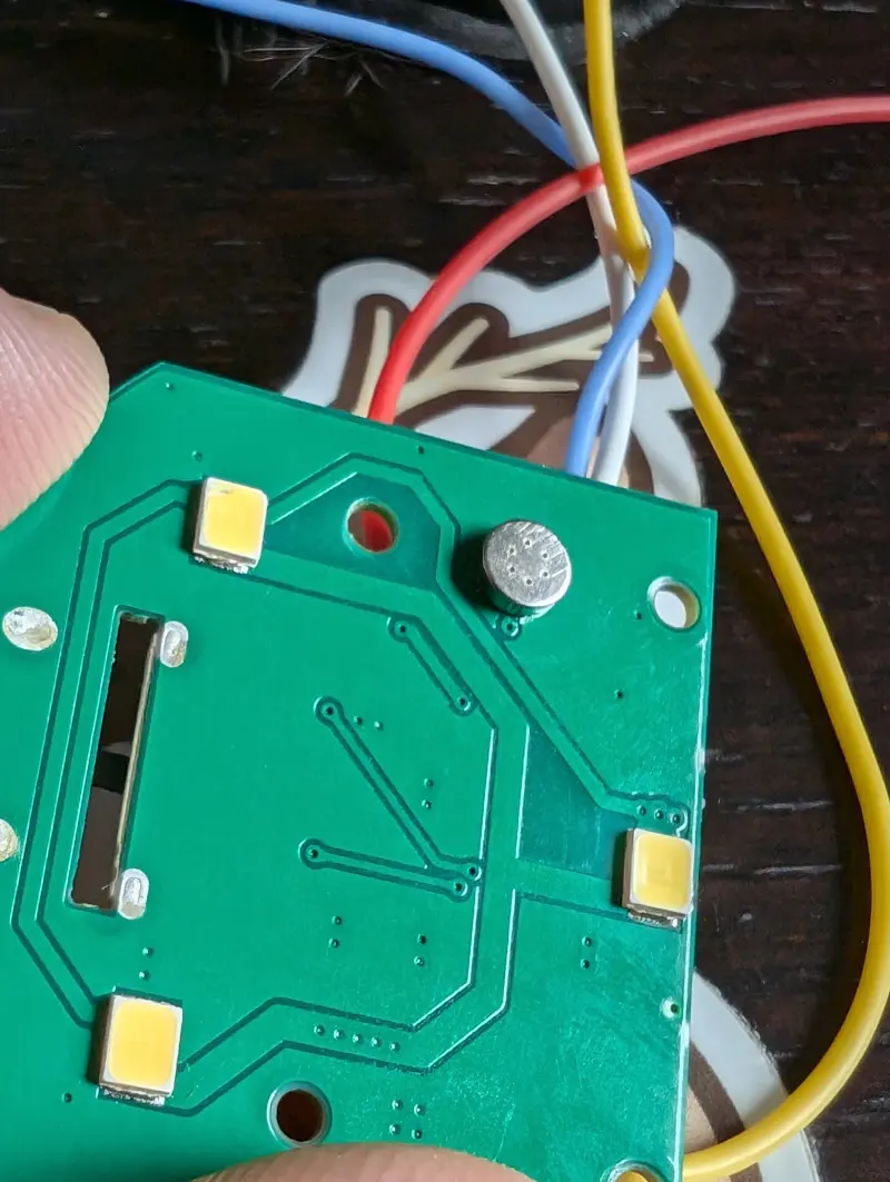
Initially, things went really smoothly. Taking it apart was easy:
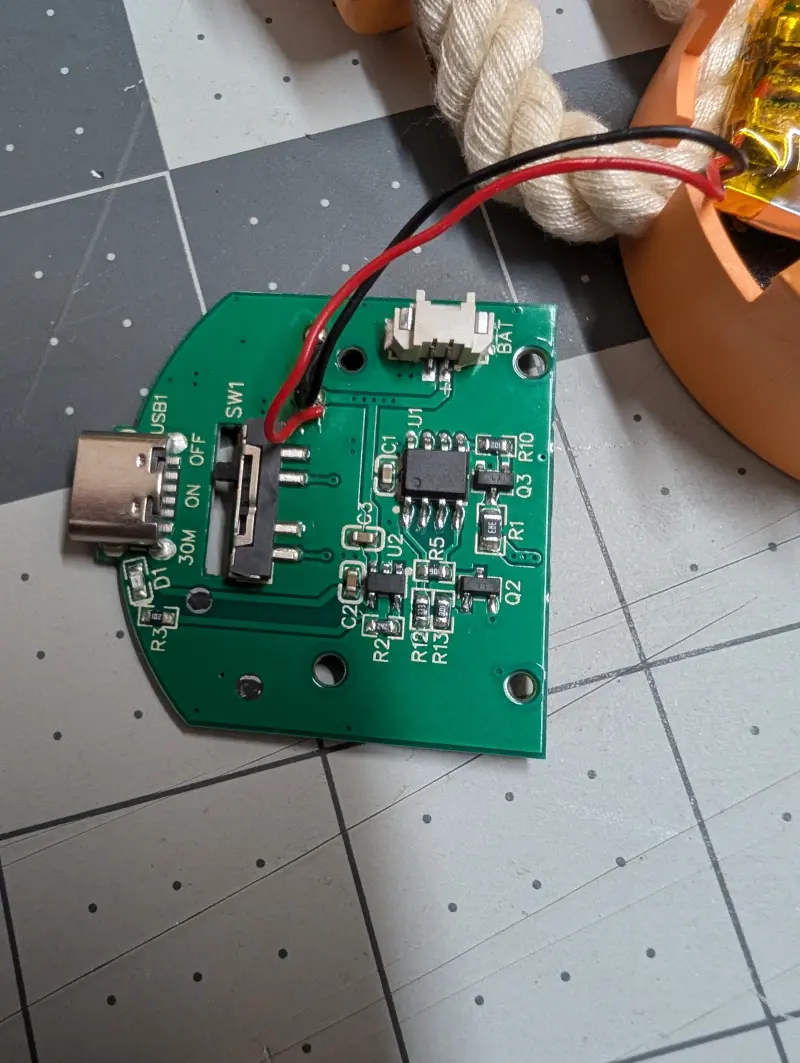
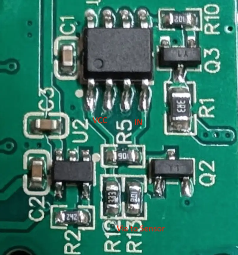
Most of the parts had labels and it was easy enough to identify the main microcontroller. Probing the pins and looking at the connections, I found:
- The board is 3.3V
- It uses a https://www.lrc.cn/Upload/PDF/Product/IC/LIB/LR4054.pdf battery charger
- The MCU uses a PWM output through a transistor to control the LEDs
- The MCU is always powered, the “power switch” actually just pulls MCU inputs to ground
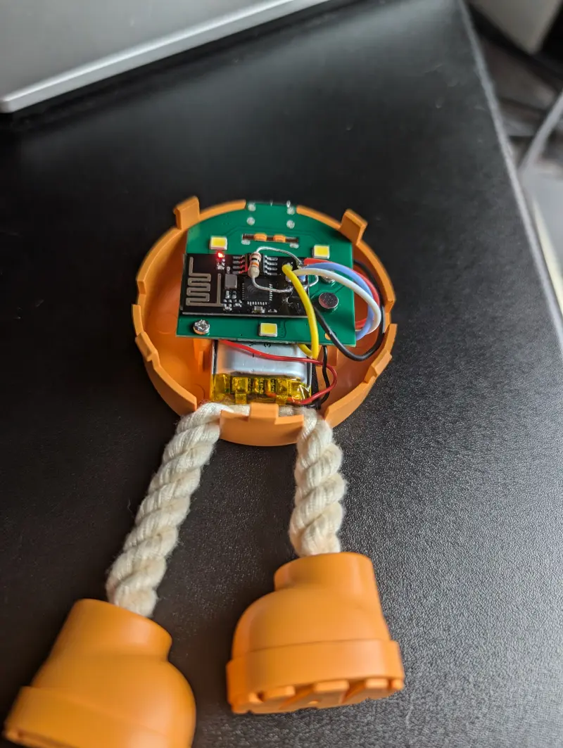
and I quickly got a basic proof of concept:
ESP-01 Initial Annoyances
Here’s where I made my mistake. I wanted to fit everything neatly inside the pumpkin, so I used an ESP-01 board.
First, just getting started with these boards is a bit of a pain in the butt. They don’t have a way to directly connect to a PC for initial programming, so you typically need to buy an adapter. In addition, the board needs a pin pulled down to put it into programming mode which the adapter does not help with. On top of this, pins need to be pulled high to boot normally. I mostly used these guides for reference:
- https://www.instructables.com/USB-to-ESP-01-Board-Adapter-Modification/
- https://www.instructables.com/How-to-use-the-ESP8266-01-pins/
Since the board is going to be inside a pumpkin, I also wanted to make sure I could get updates over WiFi working. Here I had to dig into how “over the air” (OTA) updates actually work.
Unlike the ESP32 which can use a CSV file to setup the flash layout, the ESP8266 specifies a linker script from https://github.com/esp8266/Arduino/tree/master/tools/sdk/ld. Since I wanted to use the WiFiManager library which has some relatively large dependencies, I picked a layout that maximized the size for application code. Here’s the PlatformIO configuration I used.
1
2
3
4
5
6
7
8
9
10
11
[env:esp01_1m]
platform = espressif8266
board = esp01_1m
framework = arduino
monitor_speed = 115200
board_build.ldscript = eagle.flash.1m64.ld
lib_ldf_mode = deep+
lib_deps =
  ; The WiFiManager version in the PlatformIO lib is super old.
  ; Use repo directly instead.
  https://github.com/tzapu/WiFiManager.git#v2.0.17
Since I didn’t end up getting to a complete implementation, here’s the basic code I was working with.
1
2
3
4
5
6
7
8
9
10
11
12
13
14
15
16
17
18
19
20
21
22
23
24
25
26
27
28
29
30
31
32
33
34
35
36
37
38
39
40
41
42
43
44
45
46
47
48
49
50
51
52
53
54
55
56
57
58
59
60
61
62
63
64
65
66
67
68
69
70
71
72
73
74
75
76
77
78
79
80
81
82
83
84
85
86
87
88
89
90
91
92
93
94
95
96
97
98
99
100
101
102
#include <Arduino.h>
#include <WiFiManager.h> // https://github.com/tzapu/WiFiManager

#include <ArduinoOTA.h>

// 0 and 2 are the boot select pins
// 1 is UART TX
// 3 is UART RX

// ESP01 Test
// Pull up on GPIO 2, LED on TX
#define STATUS_LED_PIN 1
#define PWM_OUT_PIN 2
#define TOUCH_IN_PIN 0

static volatile bool touch_triggered = false;
static uint8_t led_pwm = 0;
static unsigned long last_touch = 0;
static auto status_out = HIGH;

// Interrupt to call when touch pin pulled down.
IRAM_ATTR void on_touched() {
  touch_triggered = true;
}

void setup() {
  #ifdef PWM_OUT_PIN
  pinMode(PWM_OUT_PIN, OUTPUT);
  analogWrite(PWM_OUT_PIN, 0);
  #endif
  #ifdef STATUS_LED_PIN
  pinMode(STATUS_LED_PIN, OUTPUT);
  digitalWrite(STATUS_LED_PIN, HIGH);
  #endif
  pinMode(TOUCH_IN_PIN, INPUT);

  //Serial.begin(115200);

  //WiFiManager, Local initialization. Once its business is done, there is no need to keep it around
  WiFiManager wm;

  bool res;
  res = wm.autoConnect("AutoConnectAP","password"); // password protected ap

  if(!res) {
      Serial.println("Failed to connect");
      // ESP.restart();
  }
  else {
      //if you get here you have connected to the WiFi
      Serial.println("connected...yeey :)");
  }

 ArduinoOTA.onStart([]() {
    Serial.println("Start");
  });
  ArduinoOTA.onEnd([]() {
    Serial.println("\nEnd");
  });
  ArduinoOTA.onProgress([](unsigned int progress, unsigned int total) {
    Serial.printf("Progress: %u%%\r", (progress / (total / 100)));
  });
  ArduinoOTA.onError([](ota_error_t error) {
    Serial.printf("Error[%u]: ", error);
    if (error == OTA_AUTH_ERROR) Serial.println("Auth Failed");
    else if (error == OTA_BEGIN_ERROR) Serial.println("Begin Failed");
    else if (error == OTA_CONNECT_ERROR) Serial.println("Connect Failed");
    else if (error == OTA_RECEIVE_ERROR) Serial.println("Receive Failed");
    else if (error == OTA_END_ERROR) Serial.println("End Failed");
  });

  delay(500);

  ArduinoOTA.begin();

  attachInterrupt(digitalPinToInterrupt(TOUCH_IN_PIN), on_touched, FALLING);
}

void loop() {

  // This logic is to "debounce" the touch sensor since it might trigger many times for each event.
  // Basically, this only allows this to be triggered once a second.
  auto now = millis();
  auto elapsed = now - last_touch;
  if (touch_triggered && elapsed > 1000) {
    // Step up the LED brightness (PWM duty cycle) by 25% rolling back over to 0.
    led_pwm  += 64;
    last_touch = now;
    status_out = !status_out;
    #ifdef PWM_OUT_PIN
    analogWrite(PWM_OUT_PIN, led_pwm);
    #endif
    #ifdef STATUS_LED_PIN
    digitalWrite(STATUS_LED_PIN, status_out);
    #endif
  }
  touch_triggered = false;

  ArduinoOTA.handle();

  delay(10);
}
Issues Detecting Squishes
With the software all working, I could actually start putting everything together.
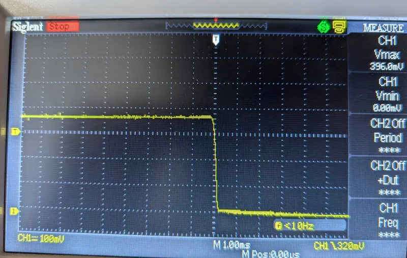
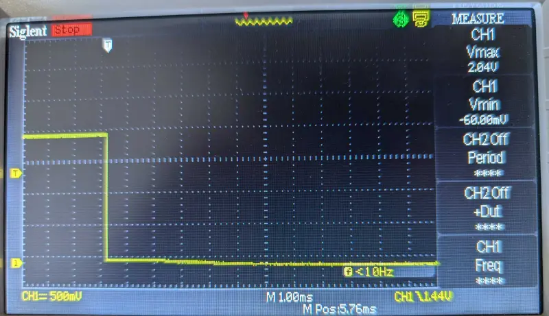
However, when I assembled it, it didn’t detect the squishes. I had initially attributed this to not being in the silicon cover, but in taking a closer look, it turned out that the voltage range was too low to reliably trigger the digital input.
Presumably, I just got “lucky” that the larger test boards that I was using was reliably registering the pulses.
The “squish” sensor was a bit mysterious. I actually made a reddit post about it. Seems like it’s a pretty clever use of a microphone as a pressure sensor.
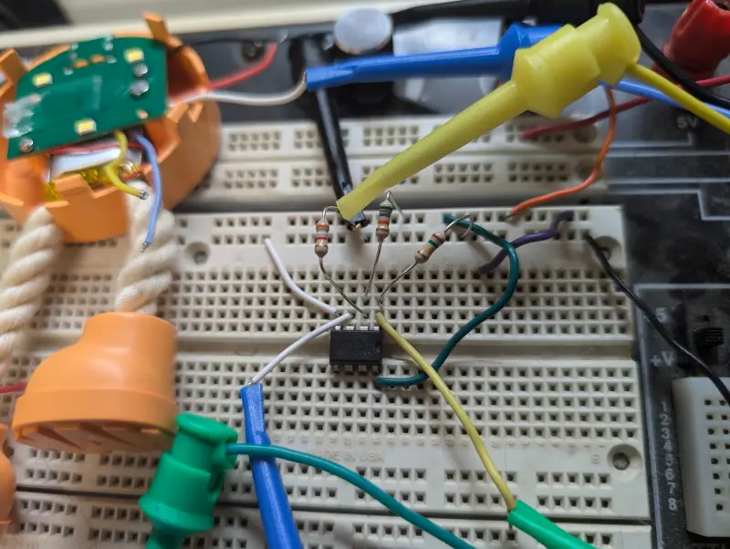
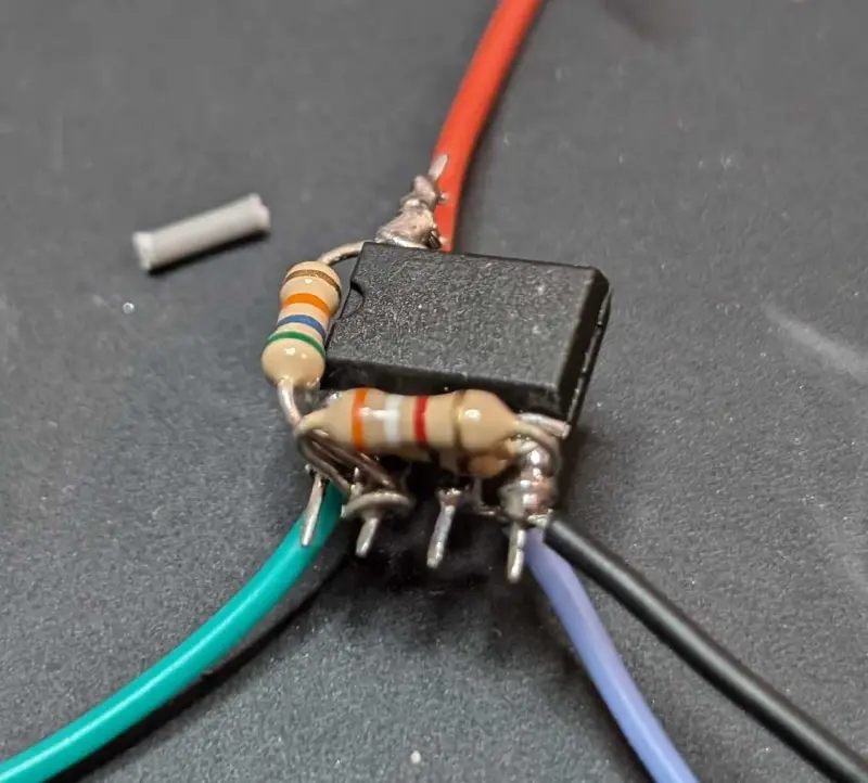
It already had a transistor, but based on the signal I was seeing, I reached way back into my college electrical engineering education and decided to use a voltage comparator https://en.wikipedia.org/wiki/Comparator.
Basically, this goes high if the input is above a threshold and is low otherwise. I’d use this as a rudimentary level shifter.
I had some op-amps lying around, and wired it up, and it worked!.
ESP-01 Too Many Annoyances
At this point, I had already spent way more time on this “simple” project than I intended, but surely now I was in the home stretch?
No, of course not. Even though everything now worked on the ESP-01 board, it would not boot after being powered on or reset.
I was able to eventually determine that this occurred if the GPIO2 or GPIO1 pins were used to output to the pumpkin’s LEDs. GPIO2 sort of makes sense since this is a boot control pin, but it was still a little surprising since it has a pull up on it.
This just left GPIO0, which seemed to work. However, when I put it all together and powered the ESP-01 off the pumpkin’s power, it once again stopped booting correctly.
At this point my hypothesis is that the voltage drop when the MCU boots and the LEDs go on was interrupting the chip’s boot process.
It wouldn’t be too hard to try to fix this by adding a capacitor or using a separate power supply, but at this point I decided to cut my losses.
My initial prototype made this seem like it would be quick and easy, but at this point I was pretty into the weeds on parts of this project that did not “bring me joy”.
In the end this was a bit of an interesting reverse engineering exercise, but I would rather move onto the next project than keep spending time on this.
