
Adding Custom Songs to a Toy Guitar
A friend wanted to use a toy guitar as a prop for a halloween costume, and they asked if I could swap out the sound effects with playing some song clips. I was happy for a project that I could fit into my limited schedule, so I gave it a go.
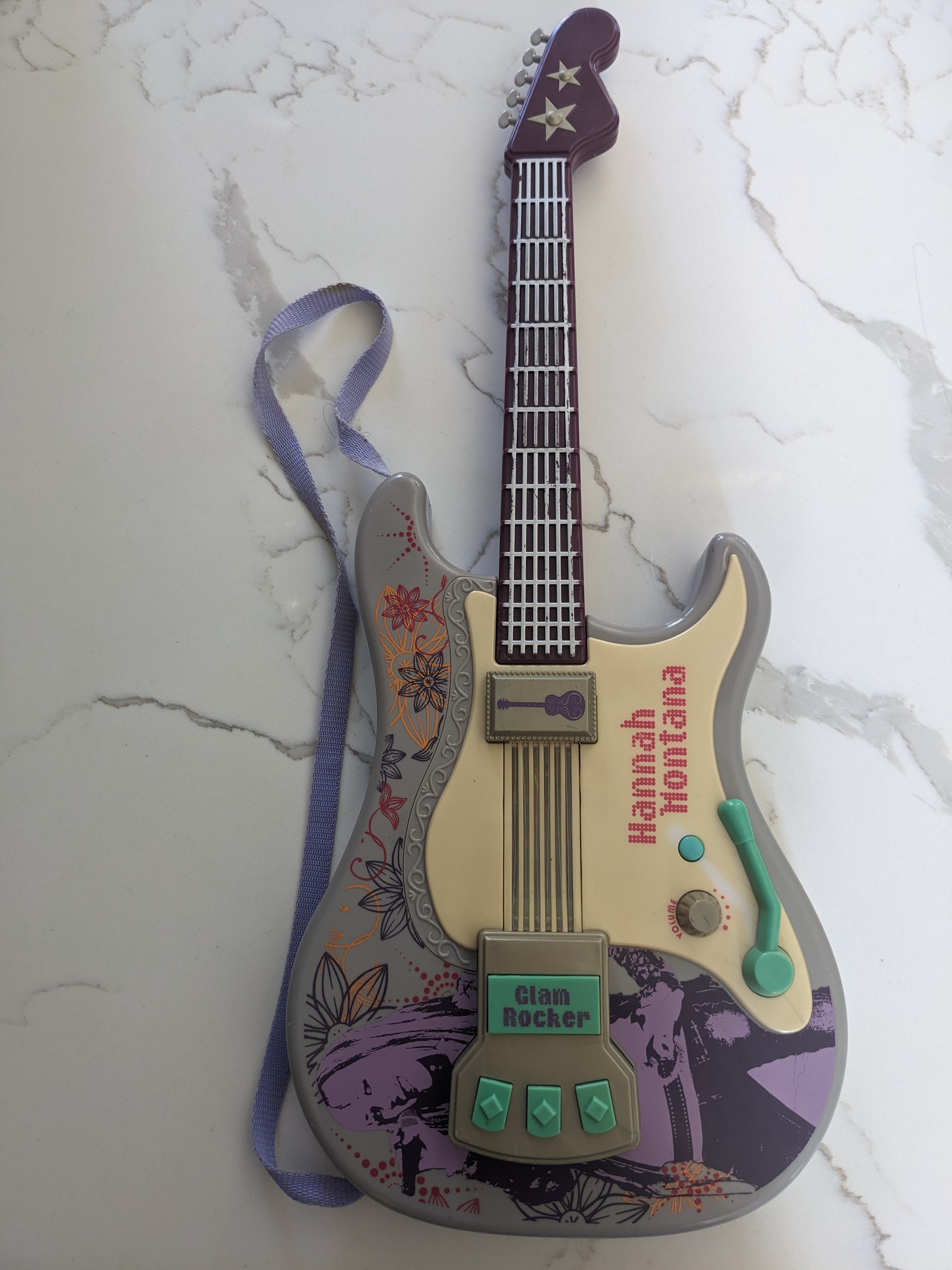
Here’s the guitar:
And here’s the final result:
The source code with comments can be found at:
https://github.com/axlan/toy-guitar
Planning Out the Modifications
While I recently had a similar project ( Giving a Toy Controller WiFi ), the goals here were different enough that I had to put in a bit of research.
As usual these days I needed to figure out how to balance making the project interesting, with the limited time I’d have to work on it. As I opened up the guitar I wanted to decide between the extremes of:
- Just using the buttons from the guitar. I’d hook them to an MCU that would send the button presses to an old smart phone to handle playing the sound.
- Use as much of the original circuitry. In some crazy world I could conceivably just update an EEPROM or flash chip with the new sound data.
Opening it up, it had a lot of empty space and the following boards:
Main Board
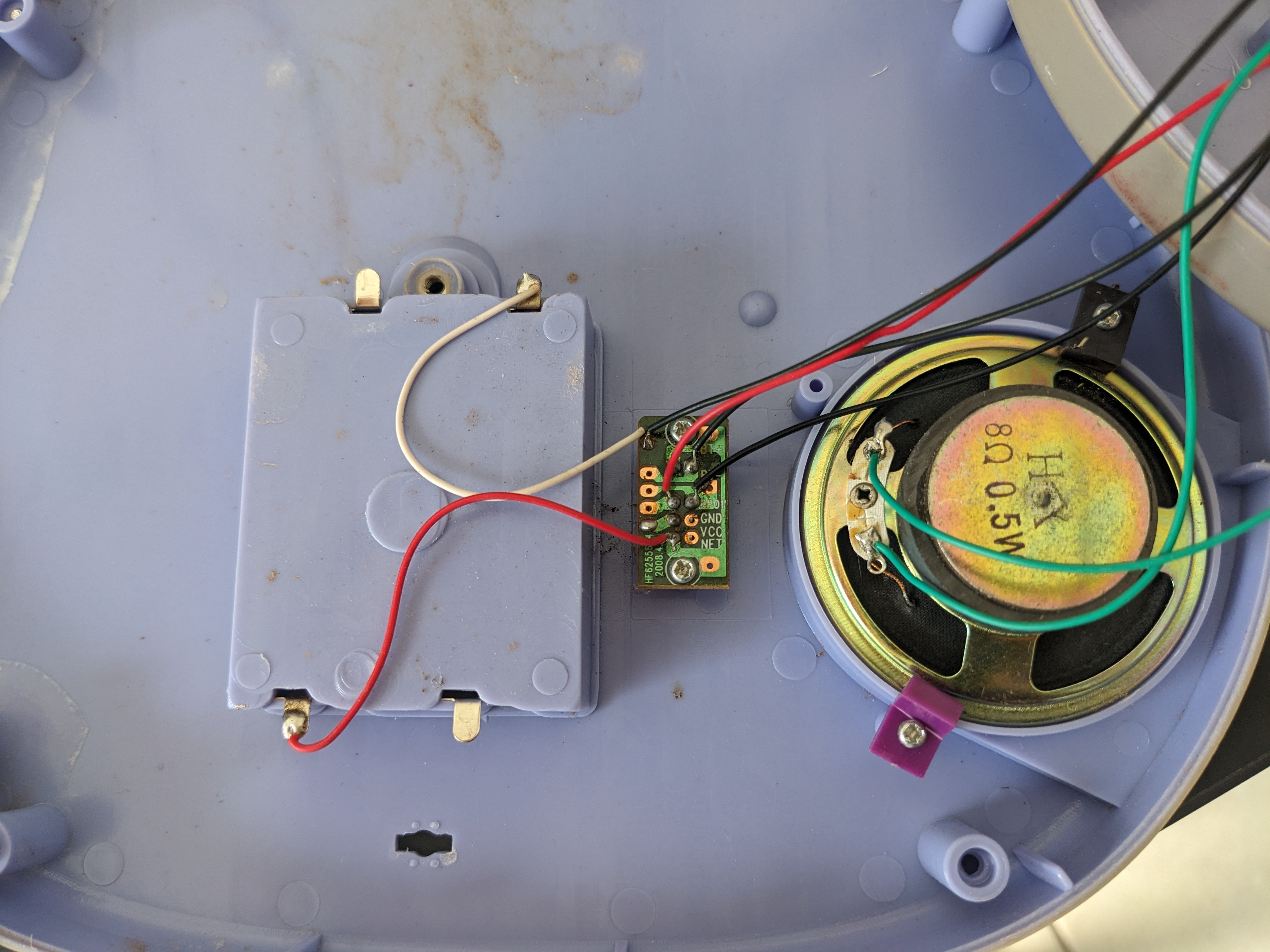
Battery, Power Switch, Speakers
Front Buttons
Strings
The plastic was in pretty rough shape and at least one of the screws was stripped. The main board was stuck on there pretty well, so I decided to take the following approach:
- Just reuse the buttons, battery, and speaker.
- Add an MCU and additional circuitry to play sounds out of the speaker
- Write code to do the following:
- Detect button press
- Read songs off an SD card
- Do the ADC conversion to play them on the speaker
To figure out how I wanted to actually do this, I started looking up examples of similar projects and seeing what parts were available. I’m going to describe this process in a pretty step by step way, but in reality there was a lot of back and forth as I traded off which approach was looking the most promising. I was trying to figure out the set of components I’d need as quickly as possible, so I could order them and start experimenting. The challenge was, that it was hard to confirm if a set of parts were going to actually work together without having a pretty good idea of the full system.
Buttons
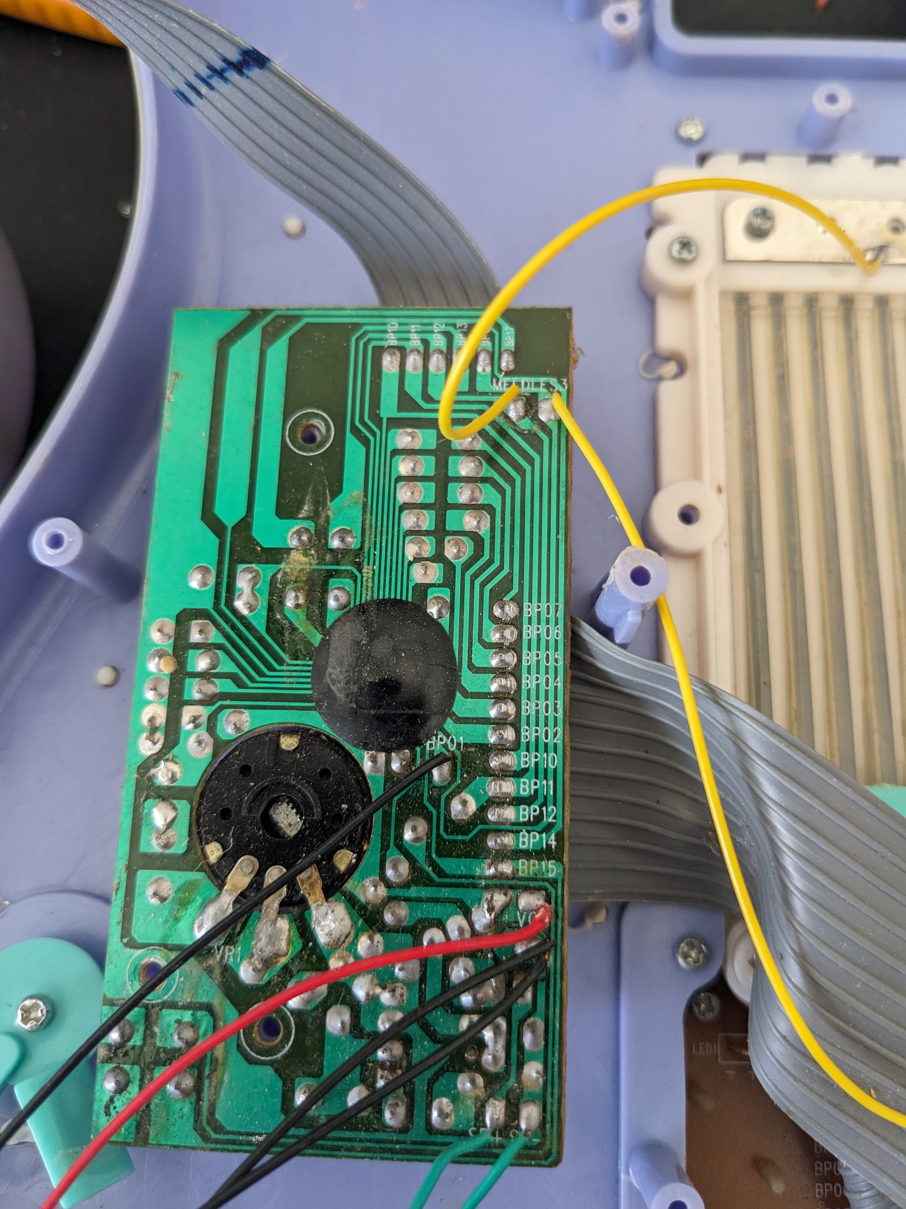
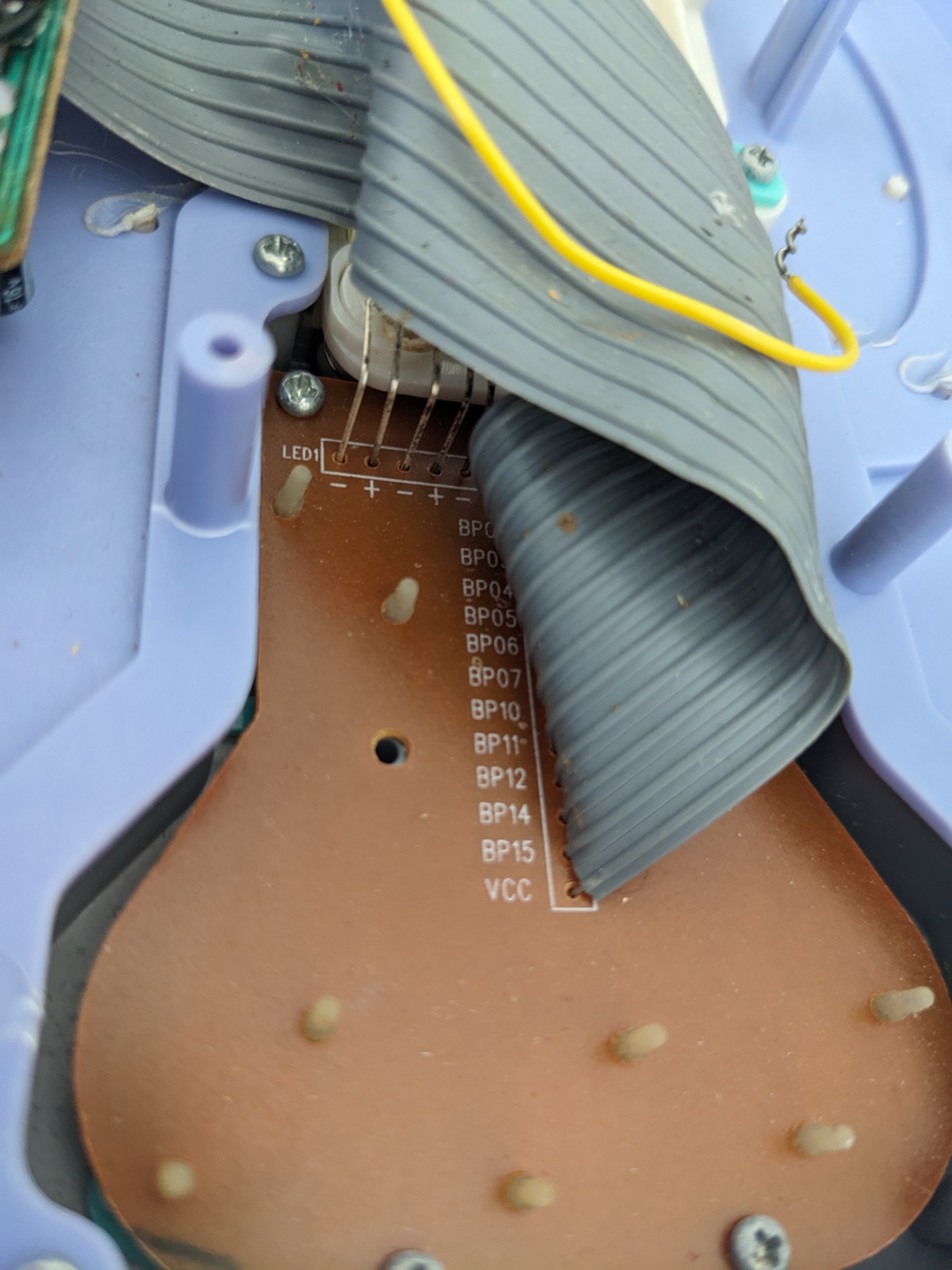
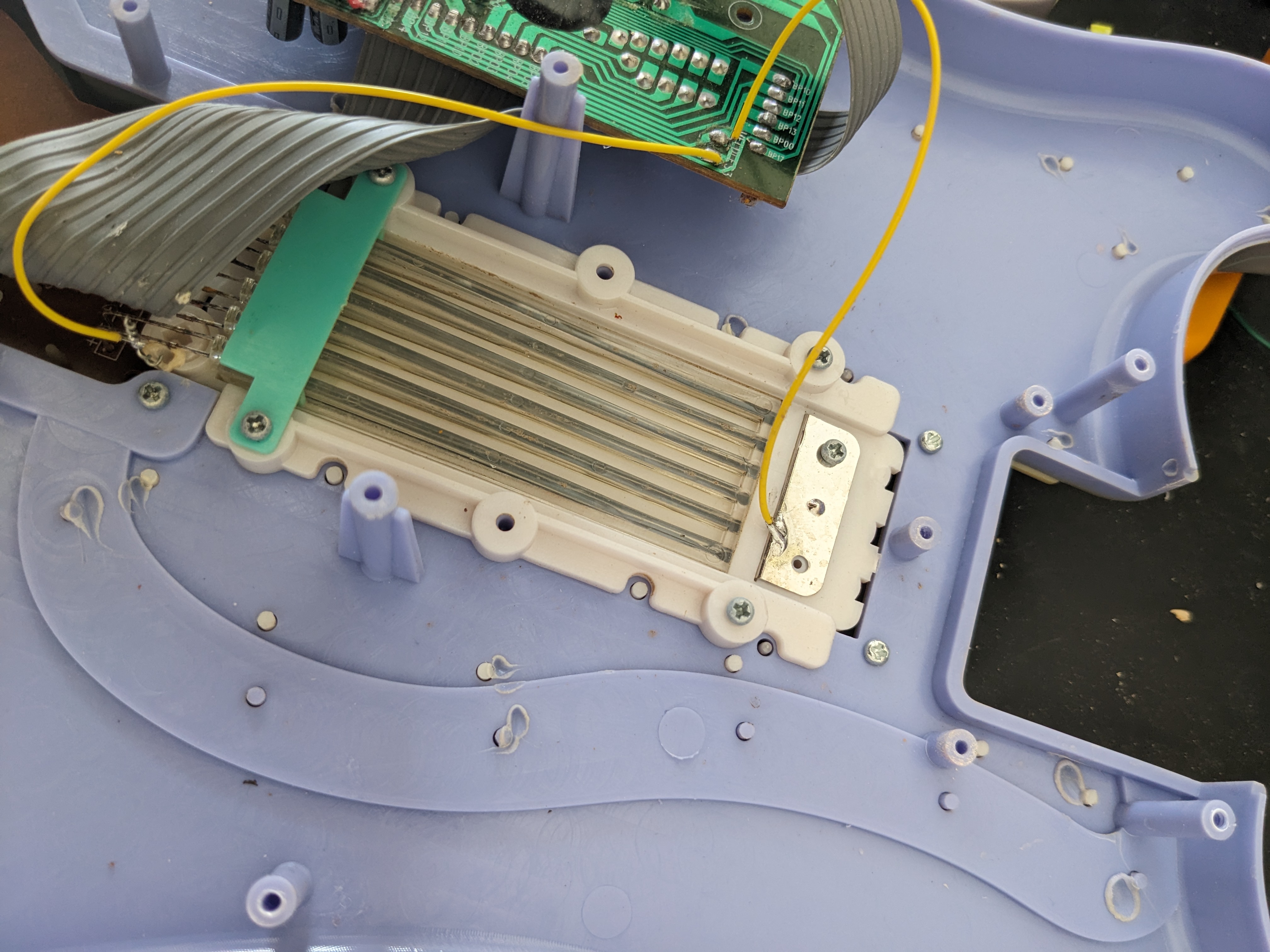
When it came to the buttons, they actually took a little poking at to understand. There were 6 buttons on the neck of the guitar I decided to use. The connector to these buttons had 6 pins. Buttons 1-4 shared pin 1 on the left side, and when to pins 3-6 on their right. Buttons 5 and 6 shared pin 2 on their left side and went to pins 5 and 6. You can actually see this in photo:
Neck Buttons
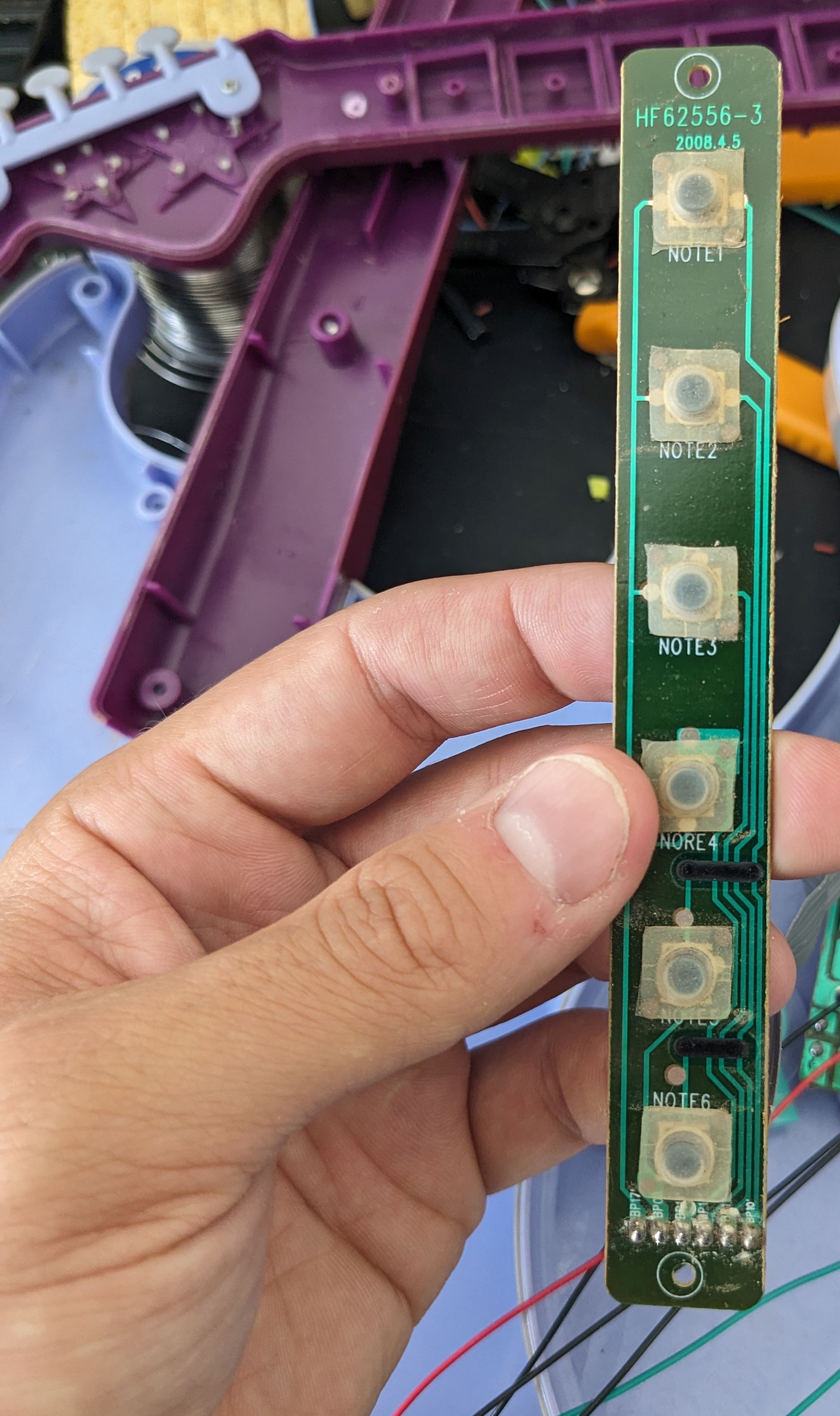
Buttons 5 and 6 used some sort of surface mount resister to “bridge” over the other traces. Looking at the rest of the design, it appears that there was some sort of strobe output that let the original controller use the same input pins to read multiple buttons based on which output it currently had high. I decided to do something similar in my design to be able to use all 6 buttons.
SD Card Reading
Surprisingly, it’s been a long time since I’ve had to read an SD card from an MCU, and I’ve never done a project that generated sound from scratch. This also presents the challenge that the SD card read rate needs to keep up with the bit rate of the audio.
Typically, embedded projects use SD cards in SPI mode, but I was concerned that this might be too low speed for sound playback. I spent some time researching using the “native interface”, but examples of how to do this were pretty spotty. Apparently, there is a built in module for this: https://github.com/espressif/arduino-esp32/blob/master/libraries/SD_MMC/README.md Since it turned out I didn’t need the extra speed, I stuck with the simpler SPI mode.
Audio Playback
Doing a little bit of research, it seems like there are 2 basic ways I could do audio playback.
- Output the sound data from a digital-to-analog converter (DAC) and use that to drive a speaker.
- Output I2S to an amplifier chip that would drive the speaker.
Since option 2. seemed a lot more likely to work out of the box that seemed like the way to go. After more research, it seemed like the MAX98357A chip was a common hobbyist component that would be able to drive the 8 Olm speaker in the guitar.
The next step was to choose the microcontroller to use. Reading an SD card and simultaneously encoding the data to I2S actually requires a decent amount of CPU power. I ended up choosing a nodemcu-32s board. I went with an ESP-32 board mostly based off this tutorial: https://www.xtronical.com/i2s-ep3/. This also served as the starting point for the code I’d end up writing.
Putting it Together
I ended up spending a decent amount of time trying to pick which pins to use. I wanted to make sure that:
- The pins I used for IS2 and the SD card would support the hardware peripherals they’d need.
- The pins I used for the buttons would be suitable for waking up from sleep mode. Ideally, they’d also support software pull-up.
Most of the board descriptions like https://esphome.io/devices/nodemcu_esp32.html or the diagrams like this:
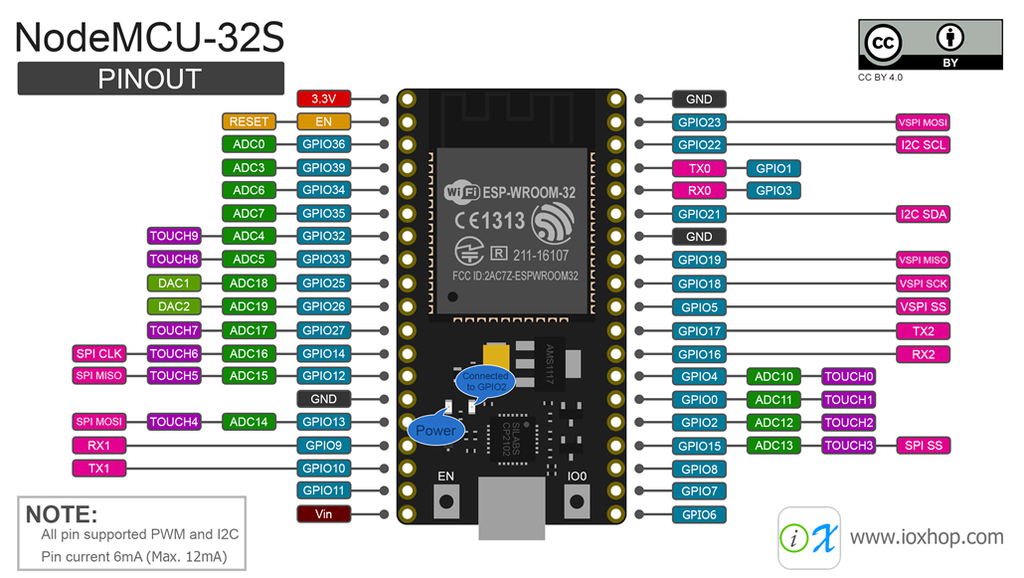
give some of the information on which pins have special features or limitations, but I needed to actually go to the data sheet for the full details.
I did a breadboard test:
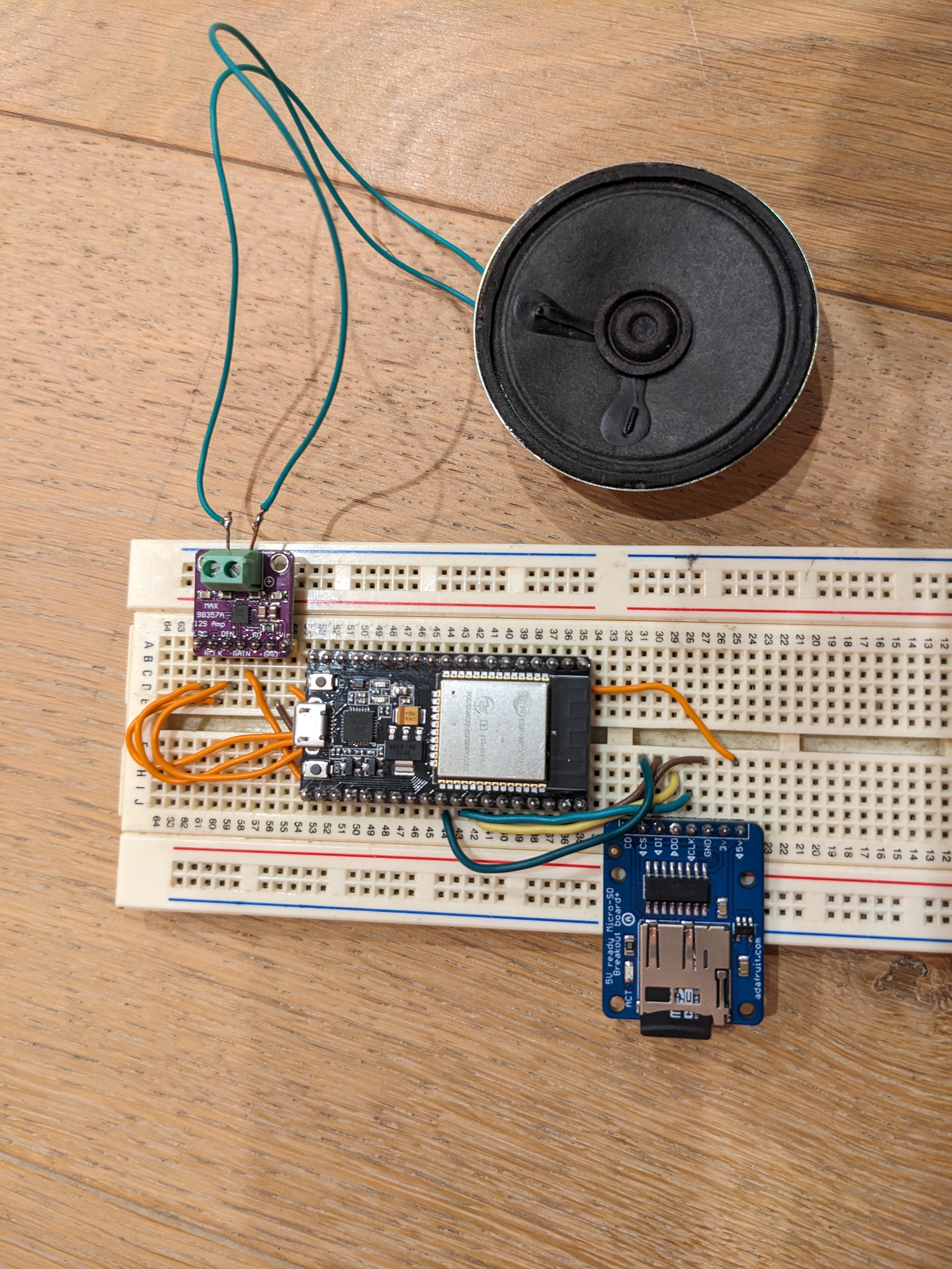
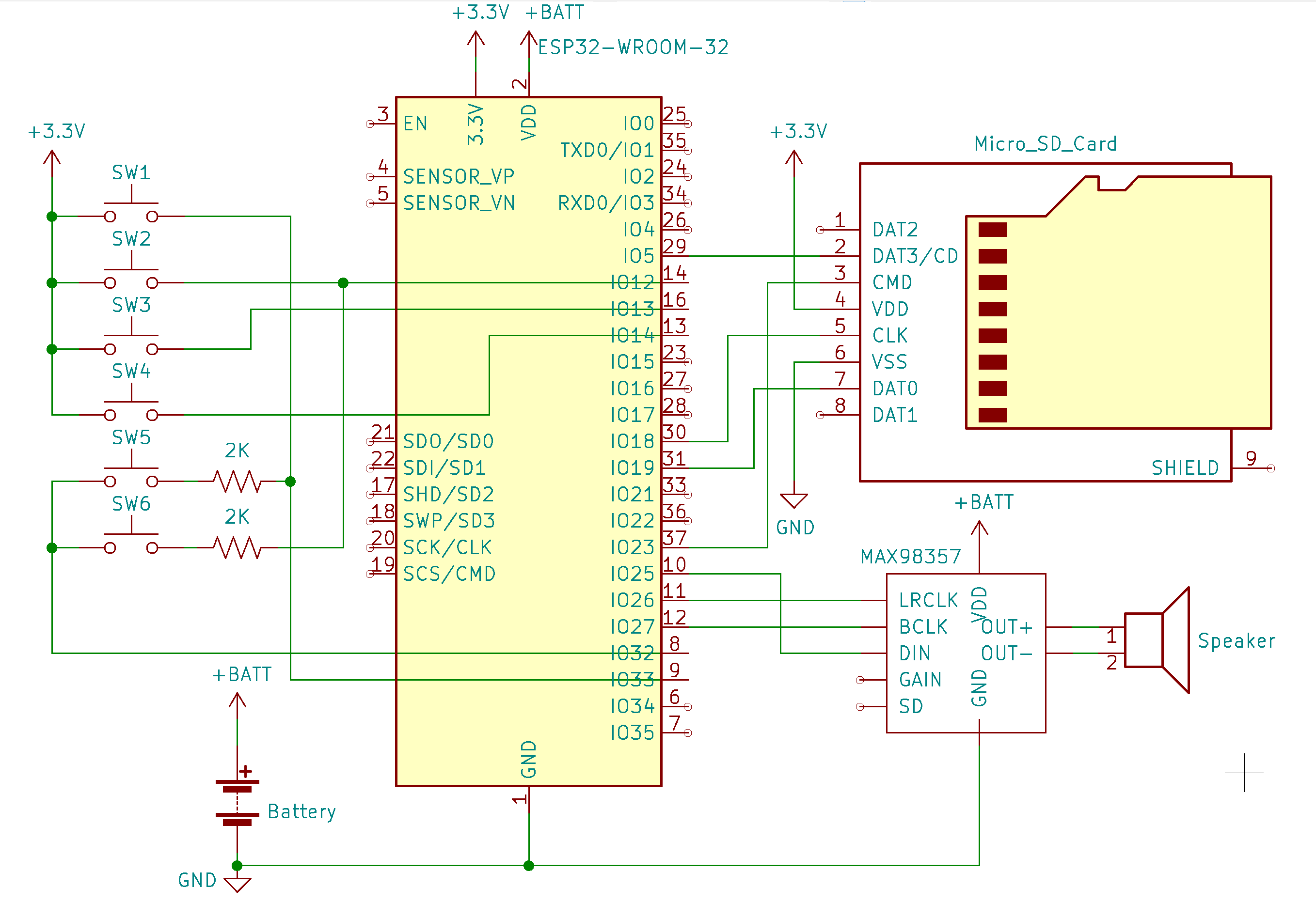
This worked pretty much out of the box, so I went ahead and put everything together to make sure that the AAA batteries would be enough to power everything. Here’s the schematic for my design:
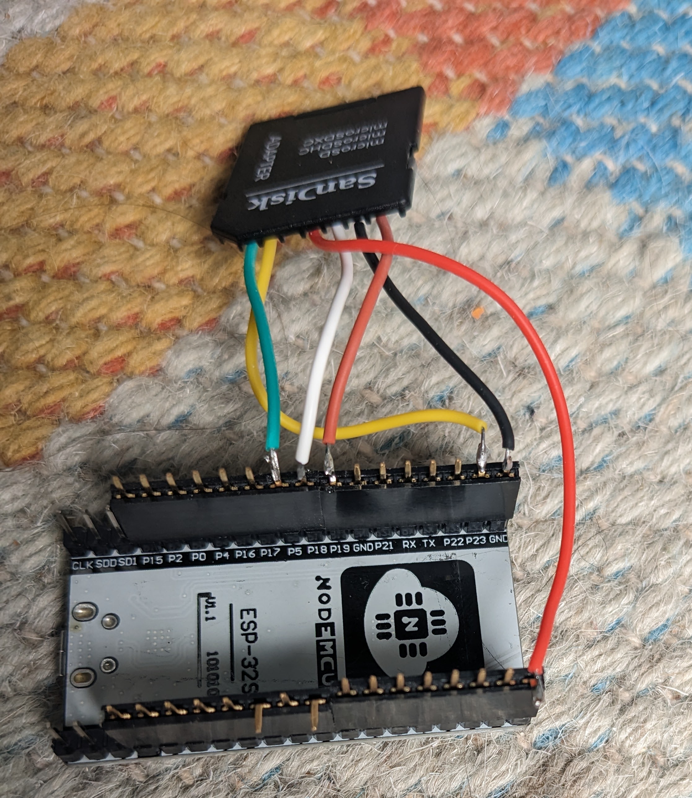
To avoid soldering directly to the ESP-32 board, I used some connectors:
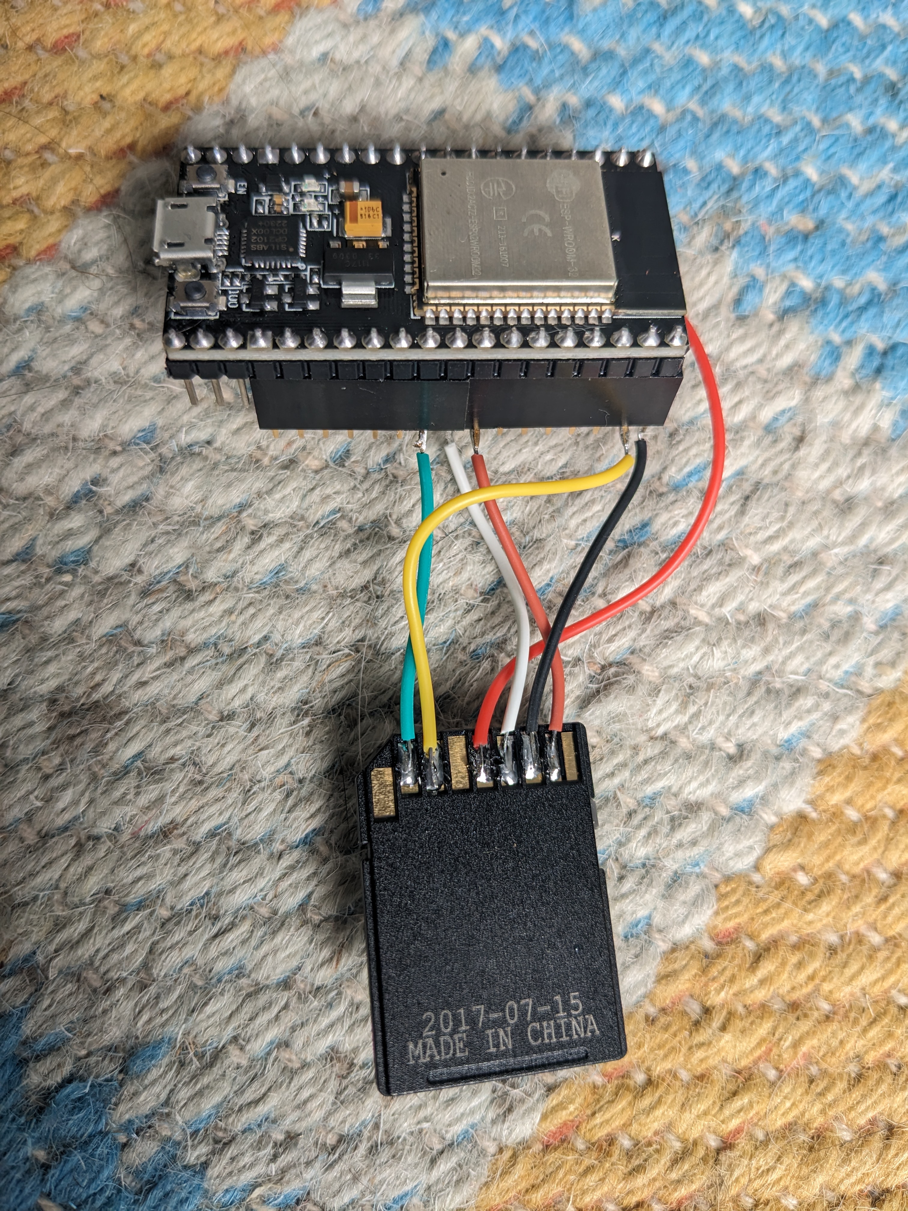
For the SD card I soldered directly to a micro SD card adapter:
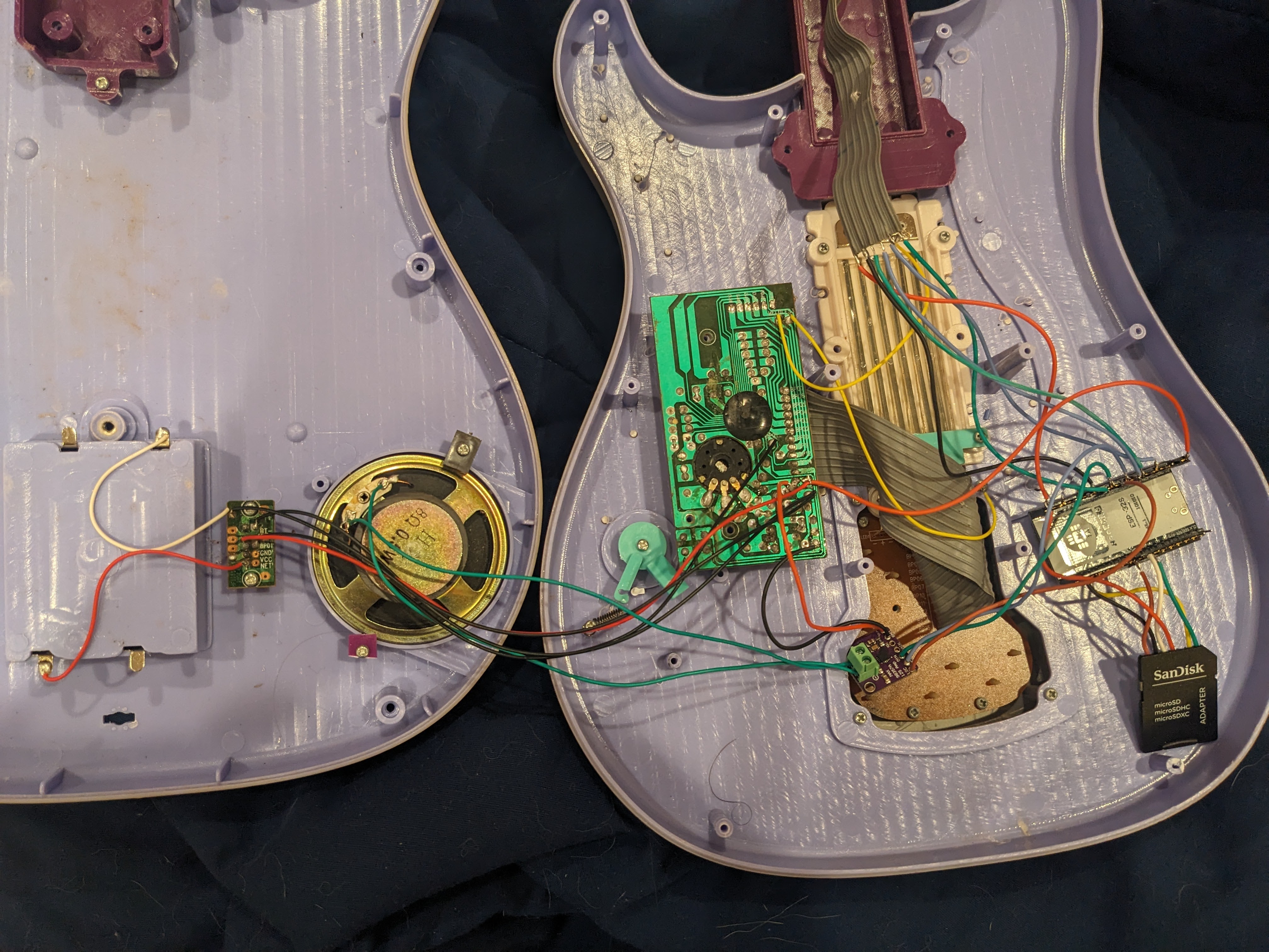
Here’s the full circuit in the guitar:
Software Development
The first thing I wanted to do, was confirm my hardware would be able to do the main task of reading data from an SD card out onto the speaker. I did a bit of googling, and was surprised there wasn’t an Arduino library that would “just work”. It seems like this is usually hardware specific enough that a general library would be pretty complicated.
As usual, I did find a library that does this after I was done and doing this write up: https://github.com/schreibfaul1/ESP32-audioI2S. I haven’t looked too closely, but it claims it does audio playback from SD cards over I2S. It does say it requires a multi-core ESP32-S3, so it still might not have worked for the hardware I was using.
I ended up starting from the example code in https://www.xtronical.com/i2s-ep3/ for my breadboard test.
The next thing I wanted to do was get the buttons working. While there were a lot of options here, I wanted to minimize the components and soldering I’d need to deal with. If you look at my schematic:
I include the logic from the button’s board. I tied the first pin to 3.3V, and I used the software pull downs on the 4 IO pins I was using to read the switches. This made it simple to detect presses on the first four buttons. To read the last two buttons, I used an additional output pin connected to the second input into the buttons. If I saw an input go high, only when this output was high, I could detect presses on pins 5 and 6. This did mean I couldn’t detect whether or not both pin 1 and 5, or pin 2 and 6 were pressed, but that didn’t matter for this application.
With this figured out, I still hit some issues with the button presses. These buttons had a lot of “bounce”. This was especially a problem with my method of disambiguating the buttons using the same pins based on multiple checks. I added a check to only confirm a button state after it stayed consistent over multiple checks separated by several milliseconds.
The next task was refactoring the audio playback code to handle starting songs based on button presses.
I pretty much redid the state machine from the ground up. I relied on the file system library to track it’s own state and switched from using static variables in the functions, to passing around a playback object to coordinate current state.
To create the sound files I’d put on the SD card, I used Audacity. While my code could handle different WAV configurations, I stuck to using mono-channel data since I only had one speaker.
After that, I was pretty much done:
Since I was in a rush, I didn’t have time to use the original volume control from the Guitar. Ideally, I would have been able to directly use the knob to control the gain input into the MAX98357A or read it’s output with and ADC. Since I wasn’t going to do more soldering, my first thought was to modify the WAV files to control the volume, but that seemed like too much manual work. I ended up writing a simple scaling function to multiply the audio samples by a fixed value as they’re read from an SD card.
Also, it seemed like a waste to use an ESP32 without adding some sort of WiFi capability. I decided to make it possible to update the firmware, and the songs on the guitar over WiFi.
To do this, I had the ESP32 create an ad-hoc WiFi access point. Once you’re connected you could access an FTP server to modify the songs. If you upload firmware.bin file, it would be used to do an update after a power cycle before being deleted. I used the FTP library https://github.com/peterus/ESP-FTP-Server-Lib which was very simple, but tripped me up for a bit since it doesn’t support passive mode which was used by default by the FTP tool I usually use (WinSCP).
To offset the power use, I also made sure the ESP32 would go to sleep after a couple minutes if no FTP connections were active and no buttons were pressed. I used the article https://www.upesy.com/blogs/tutorials/how-to-use-deep-sleep-on-esp32-to-reduce-power-consumption#use-several-gpio-pins-to-wake-up-the-esp32 as a reference for setting the sleep and wake up.
The source code with comments can be found at: https://github.com/axlan/toy-guitar