
Traffic Costumes
For Halloween this year, my family went as traffic controls. In particular, I made a traffic light costume that changes color based on my daughter’s movement.
Here’s the full family:

and here’s the traffic light in action:
All code for this project can be found at https://github.com/axlan/traffic-light-costume.
In the end, I basically made a low power and cost GPS position logger with a few costume specific features.
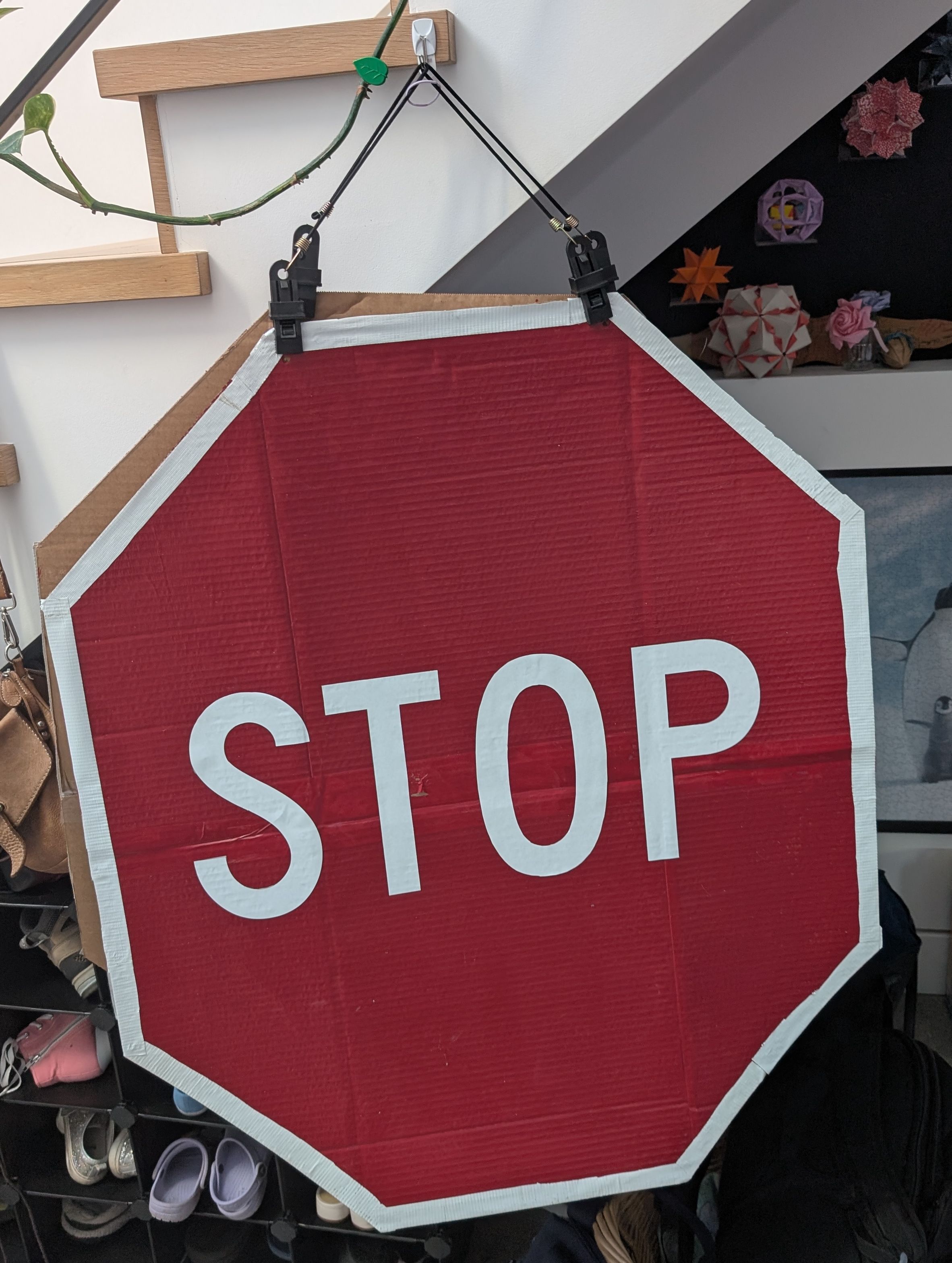
Making the Stop Sign Costume
- Cut up some cardboard boxes into half octagons
- Taped them together
- Painted them red
- Printed and cut out the letters using the font “Highway Gothic Narrow”
- Glued the letters on
- Made a border with white tape
- Attached straps using bungee cords

Making the Traffic Light Costume
My original idea was to use an accelerometer to determine when the lights should change. My hypothesis was that I could use the magnitude of the x, y, z acceleration as a rough proxy for movement. When walking there’s a lot of up and down movement that would probably be sufficient to discriminate between moving and standing still.
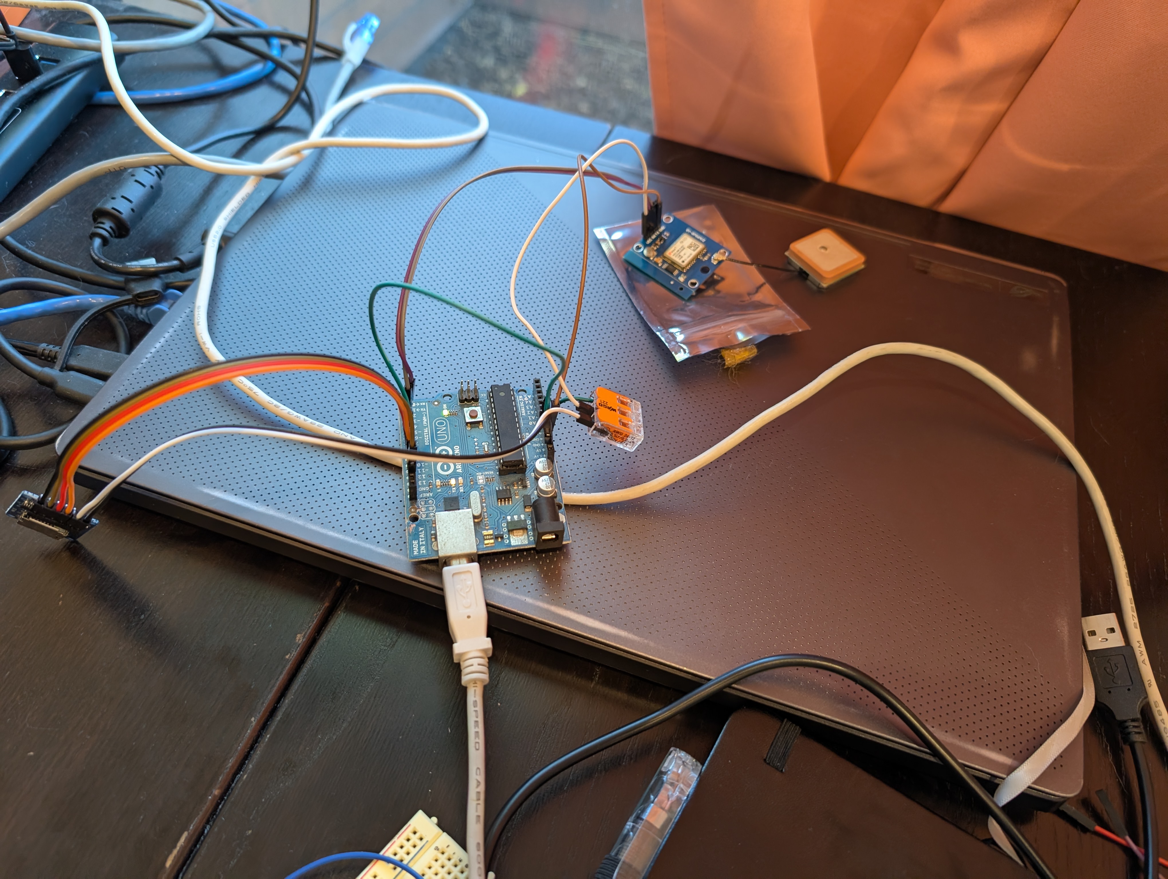
I did some prototyping using an Arduino and an old IMU. I was disappointed that it didn’t just work and there was no response from the IMU. Rather than spend a bunch of time debugging the SPI interface, IMU driver, and the hardware, I decided to go with a backup approach.
Testing the GPS Receiver
I had gotten a u-blox GY-NEO6MV2 GPS receiver (or probably a clone) for a couple bucks a while back. These modules communicate using the NMEA protocol over UART, which makes it straightforward to read velocity. This also meant I could log position and generate a map of the trick-or-treat route. This does come at the cost of not working indoors, and not working well if there isn’t a clear view of the sky.
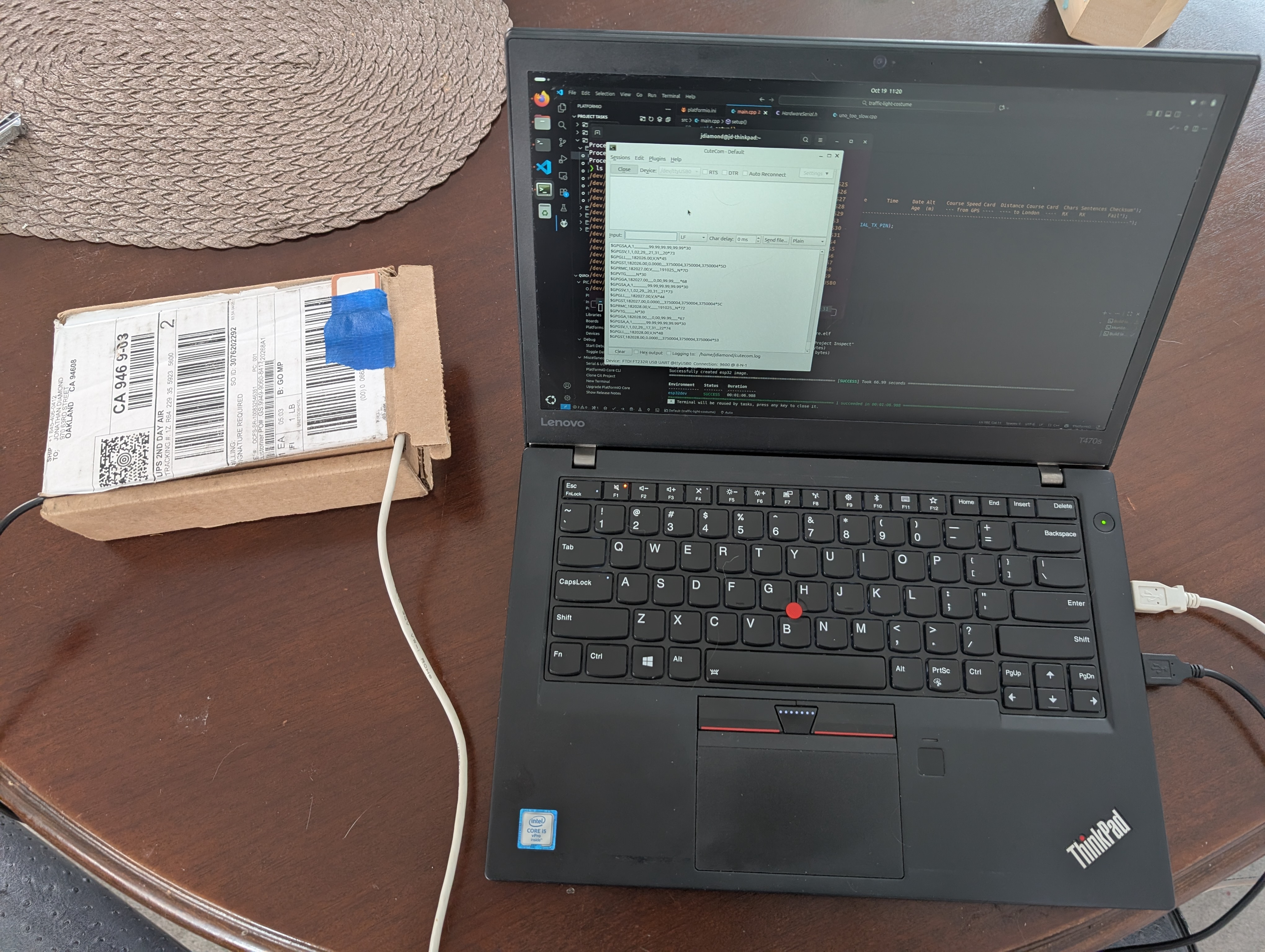
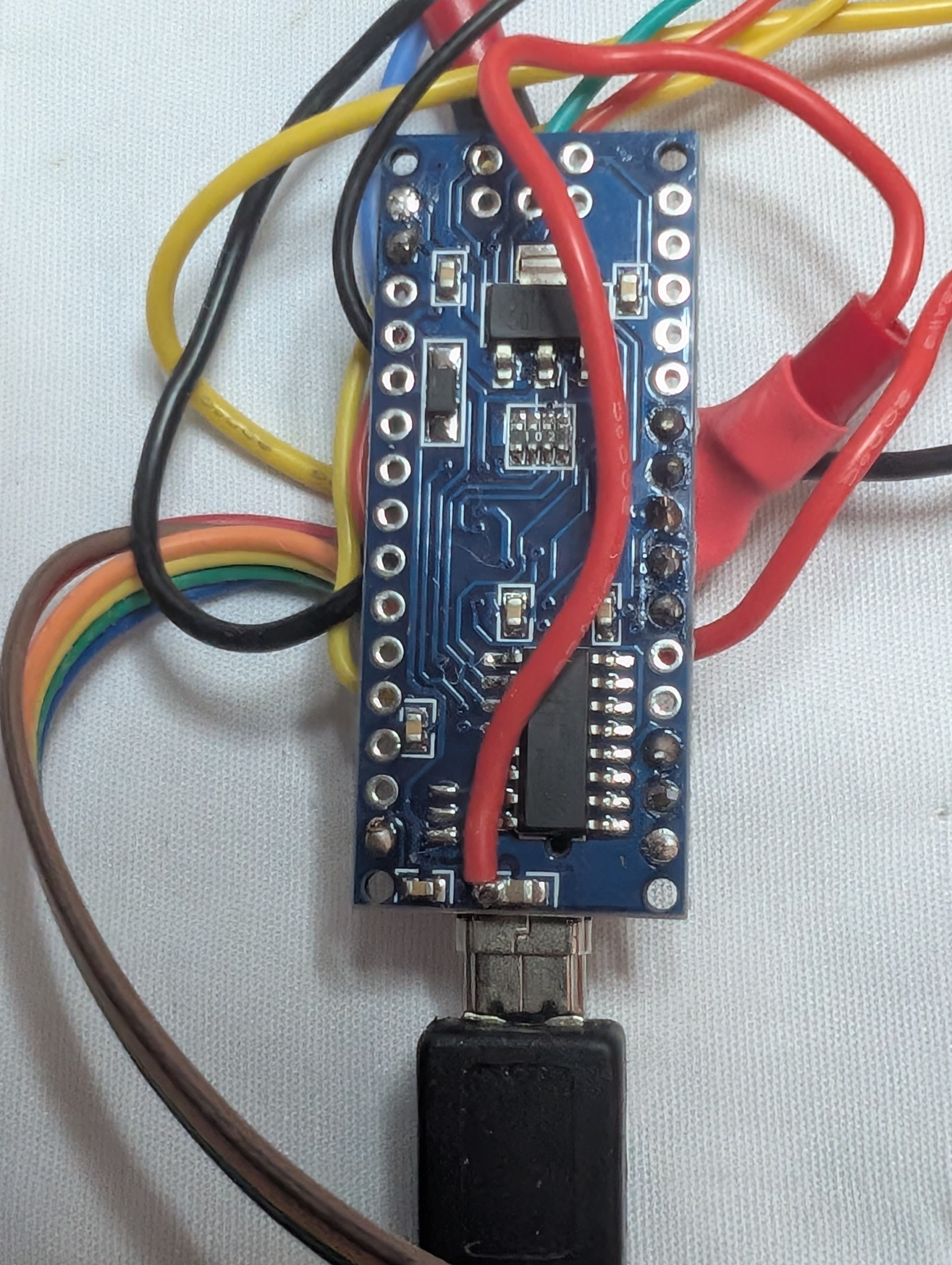
The first thing I did was configure and test the GPS receiver by itself. I used a USB-to-TTL adapter to connect the receiver directly to my computer and the u-blox GUI u-center to get status and configure the unit. I changed the UART baud rate and customized the messages the receiver would send.
To test it “in the field”, I stuffed it into a box and used an Arduino as a power supply.
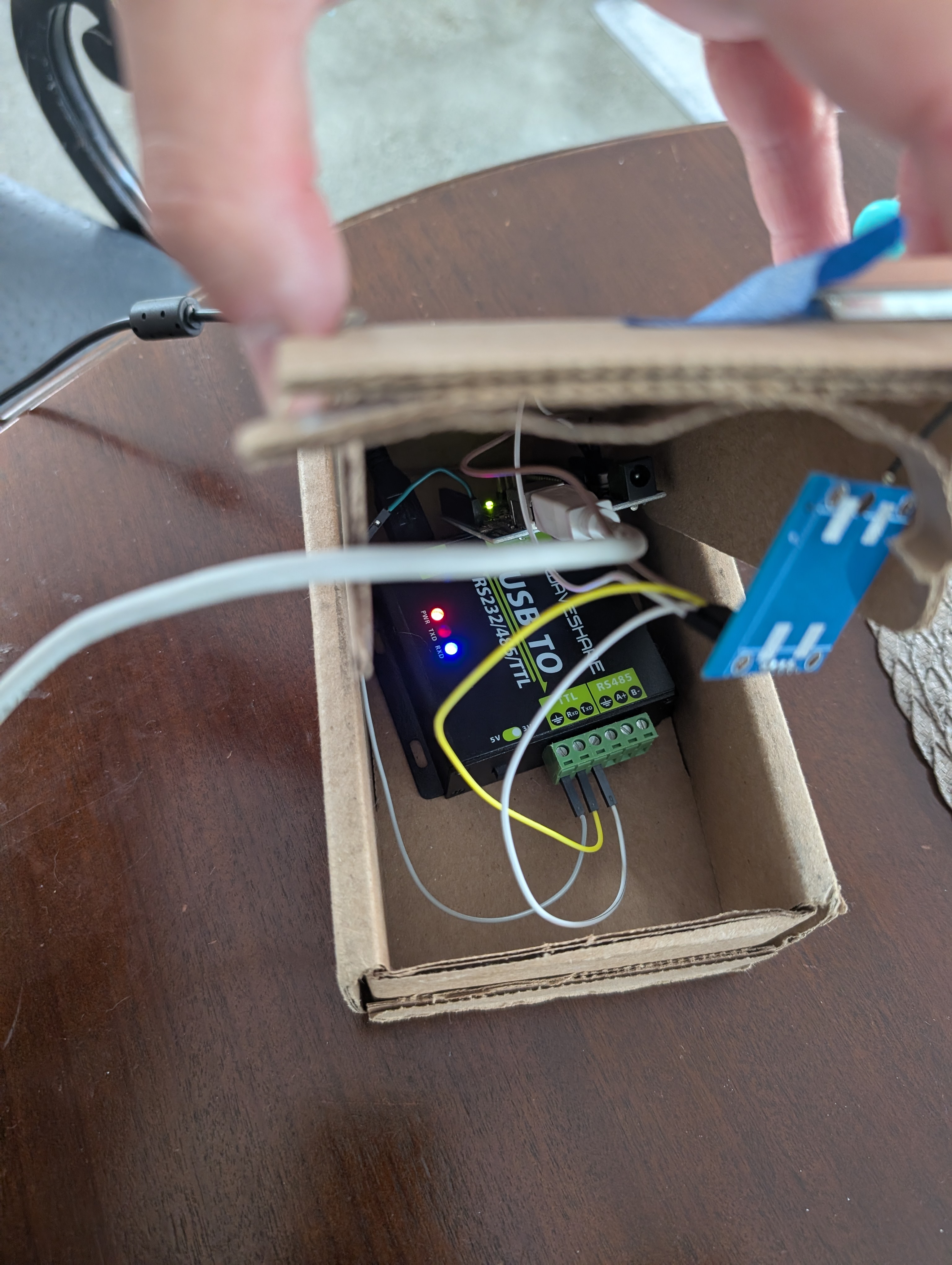
I took it for a walk to get a sense of how well it would work in trick-or-treat conditions. It performed reasonably well. Positions would jump if houses or trees blocked the sky, but the velocity was stable enough when averaged over a few seconds.
Building the Costume Circuit
For the version that went in the costume, I wanted to use an Arduino Nano. They are small and low-power, and I had one on hand. I found some older boards had inconsistent support in current Arduino tools and documentation. I had trouble finding schematics and documentation on which pins were associated with the SPI interface.
Getting the GPS talking with the Arduino was straightforward using a software serial port (there was only one hardware UART, which I used for debugging). I initially used the TinyGPS library, which made basic verification easy. The baud rate I used for PC testing, 115200, was far too fast for the Arduino’s SoftwareSerial port. It constantly dropped data, so I switched down to 9600 baud.
Similarly, getting the SD card working was simple; the built-in SD card library worked out of the box.
While I originally considered making the costume from scratch, that wasn’t the part I was most interested in. Building something sturdy enough to wear is its own challenge (foreshadowing for later problems), so in the end I bought a costume for $30. The original costume had a control box for the lights with a connection for each light and a common ground. A little testing showed the box was just directly wired to the LEDs, and the LEDs drew low enough current that I could drive them with Arduino GPIO pins using a 500 ohm resistor in series for each LED.
While getting each component working individually went smoothly, I spent a lot more time than expected integrating everything.
The first issue was that the Arduino wasn’t fast enough to log the raw GPS NMEA data to the SD card. To improve efficiency, I cached position and speed (updated once per second) and performed bulk writes every 30 seconds.
Even with reduced write frequency, I still saw unexpected crashes. My best guess was that memory usage between the GPS, software serial, and SD libraries was too much for the small processor. I wrote a minimal NMEA parser that only handled the one message I needed (RMC). With that, I was able to write firmware that handled the costume’s complete functionality.
The final firmware is the PlatformIO project at https://github.com/axlan/traffic-light-costume.
With the hardware assembled, I put it all together:

I powered everything from a USB battery pack. I had a large one that reported nearly no drain after running for a couple of hours.
Once assembled, I started noticing power-related issues. The SD card would often fail to be detected. After debugging, I realized the VIN pin on some Arduino Nano boards couldn’t supply enough current for the GPS and SD card. Something in the onboard power conditioning couldn’t handle the load. Powering the SD and GPS directly from the USB 5V line fixed the issue.
As I mentioned earlier, I did have some durability issues with the costume. Some of the cabling between the Arduino and the GPS proved fragile and occasionally needed to be wiggled to restore the connection. In hindsight, I should have kept the GPS closer to the microcontroller rather than mounting the receiver up near the top for a better antenna vantage point. A shorter, more secure cable run or a sturdier connector would have been a better choice. Fortunately, it held together for the actual trick-or-treating run.
Processing the Data
The data is logged if a FAT32 formatted SD card is in the costume when it boots. It creates filenames like “log000.bin”, “log001.bin”, etc. each time it powers up. Each binary file contains latitude, longitude, and velocity as four-byte floating-point values.
I created a Jupyter notebook (https://github.com/axlan/traffic-light-costume/blob/master/python/analysis.ipynb) to load the data and generate plots and maps.
