
Wreath Pixel Display
This idea was based on the concept of making a “Sound Catcher” pixel display. I’ve been wanting to make this for a long time, but only recently made the time to put it together. I originally wanted to turn this into a display for ambient sound in the room, but ended up making it into a general audio display and clock.
The video starts off with the display in clock mode, before showing the FFT of a song being chromecast onto a TV. The audio out is sent to the display. I also use a web UI to change displays and set the brightness.
Hardware
In designing the hardware, I focused on using parts that had a lot of functionality with minimal hardware complexity.
The two main components are:
96 WS2812B RGB LED breakouts (https://www.amazon.com/dp/B00P2GQUYC) – These things are really neat. They are RGB LEDs with built in controllers. This lets the full range of color and brightness to be used with only a single digital control pin. The LEDs can be also form a chain so a single output from the MCU can control all the LEDs. The Arduino FastLED library makes control very straight forward.
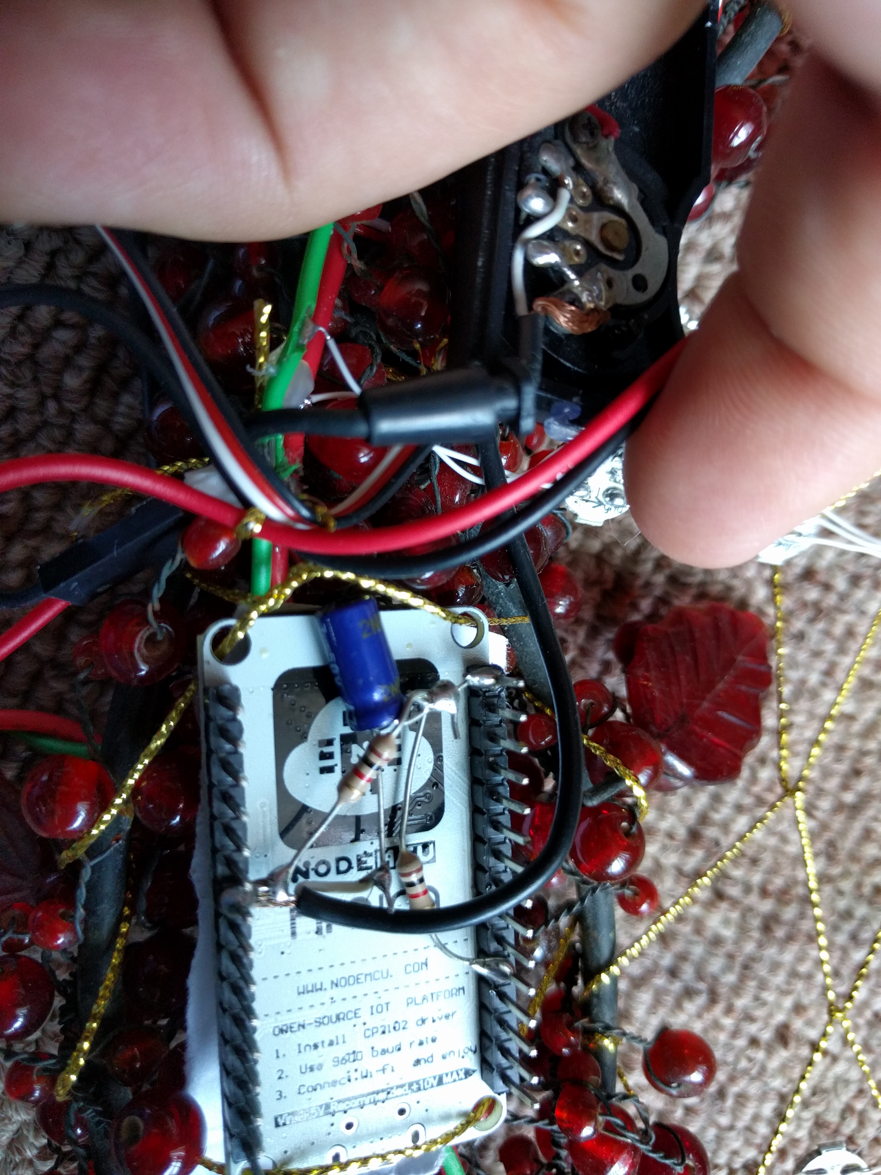
A NodeMCU ESP8266 breakout board (https://www.amazon.com/dp/B010O1G1ES) – The ESP8266 is an amazing chip that is an MCU with built in WiFi capabilities. The NodeMCU board was a nice balance of cost/convenience when I got it. The important feature is that it breaks out the analog input pin to use as an ADC for the sound input. There are Arduino libraries that do the heavy lifting for over the air updates and running a web server.
To power all the LEDs I got a 5V 6A DC power supply (https://www.amazon.com/gp/product/B01D8FM4N4) I’m sure there are cheaper options out there, but this was the first high power 5V supply I found. I figured max current usage would be something like 20mA * 3 * 96 = 5.76A . I never plan on having everything on full so there should be plenty of power for the controller. I’m still a little concerned that the MCU power has no isolation from the LED power since I’d guess things could brown out if a large chunk of LEDs switched at once.
The stereo to mono jack was some piece of junk I had lying around and I mounted the whole thing in a wreath I found at a thrift store years ago.
Since the ADC in the NodeMCU has a 3.3V reference I built a circuit to add a ~1.65V bias to the incoming audio. I tested this out with my new scope http://robopenguins.com/2017/05/18/new-scope/ . When I had things working, I soldered the parts dead bug style to the underside of the NodeMCU board.
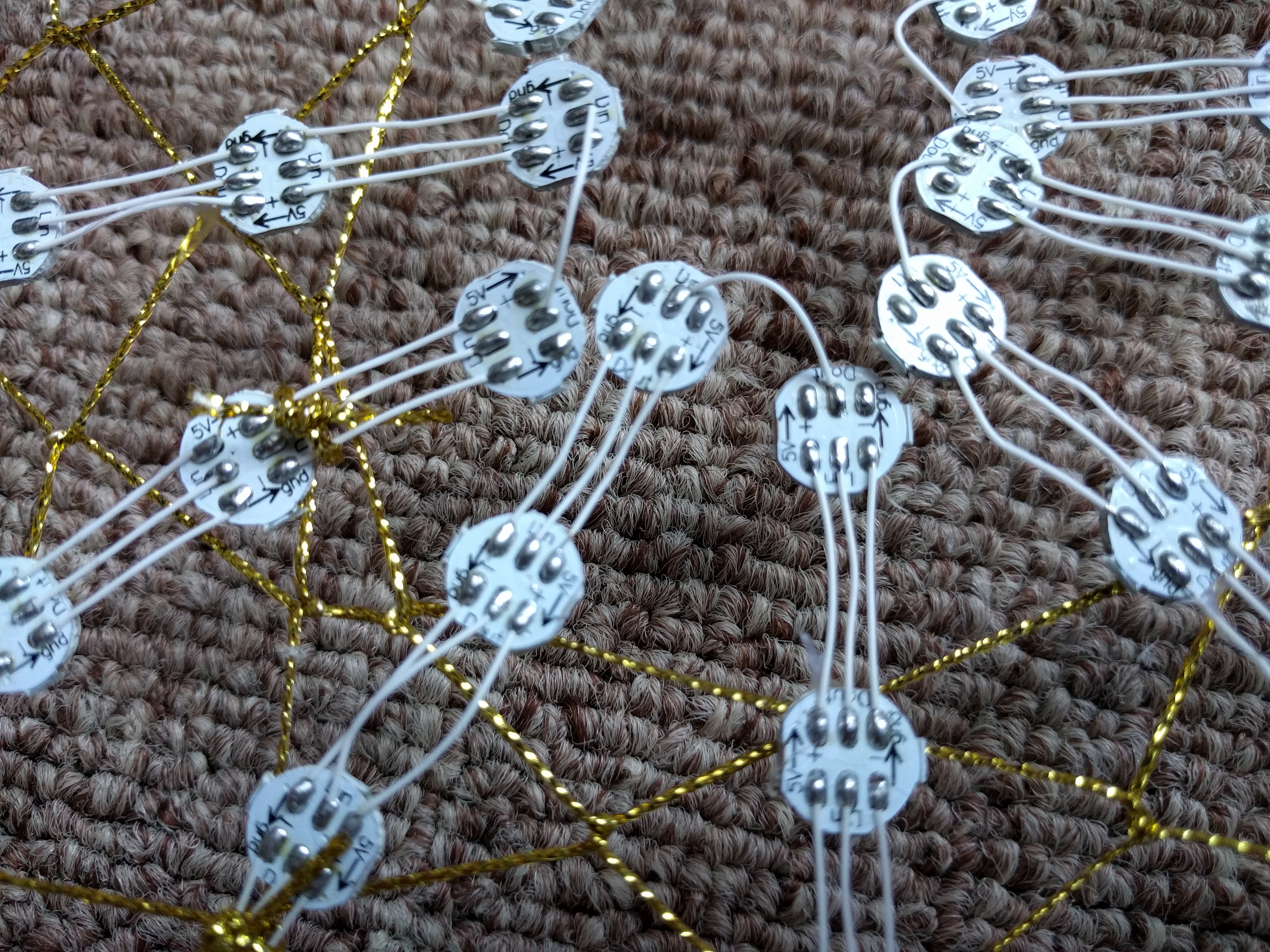
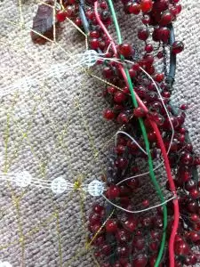
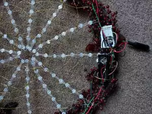
By far the most time consuming part was wiring the thing up, and in retrospect using LED strips would have probably been the more practical solution. I first soldered the 6 pads of each LED and cut and stripped the hundreds of little wire segments. I then constructed the 8 LED long segments. The design of the LEDs makes these series chains convenient, just needed to line up the arrows.
To keep with the idea of a dream catcher made to capture sound, Maria wove a dream catcher that I tied the strips of LEDs to based on one of the many instructional videos on Youtube.
To power everything I added larger pieces of wire along the border these attached to each strip in parallel to minimize the amount of power that needed to go through the thin wires making up the LED strips.
The circuit (including the stereo to mono box) is as follows:
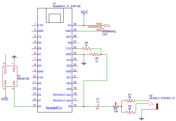
Note that the LED array would repeat 96 times.
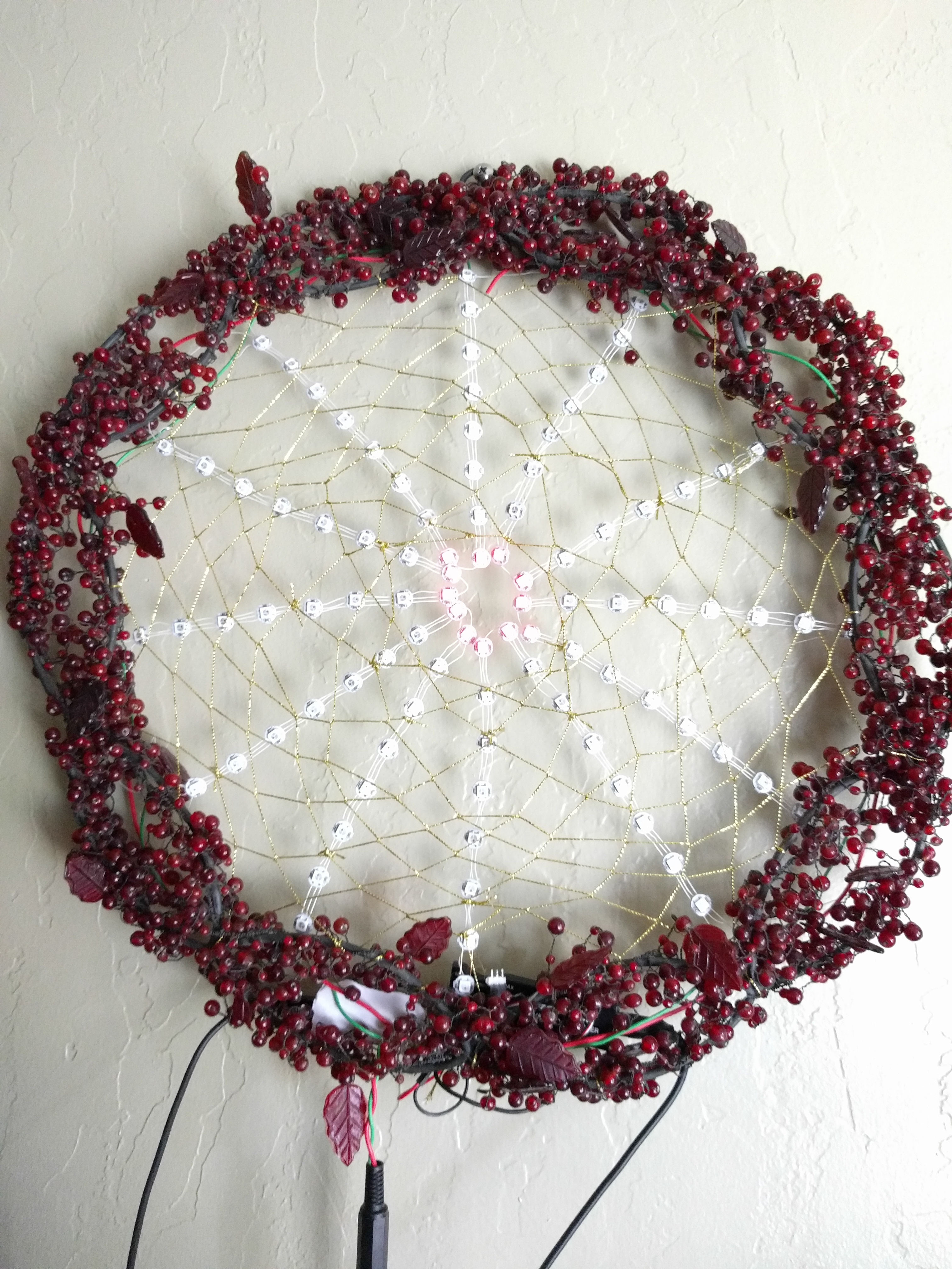
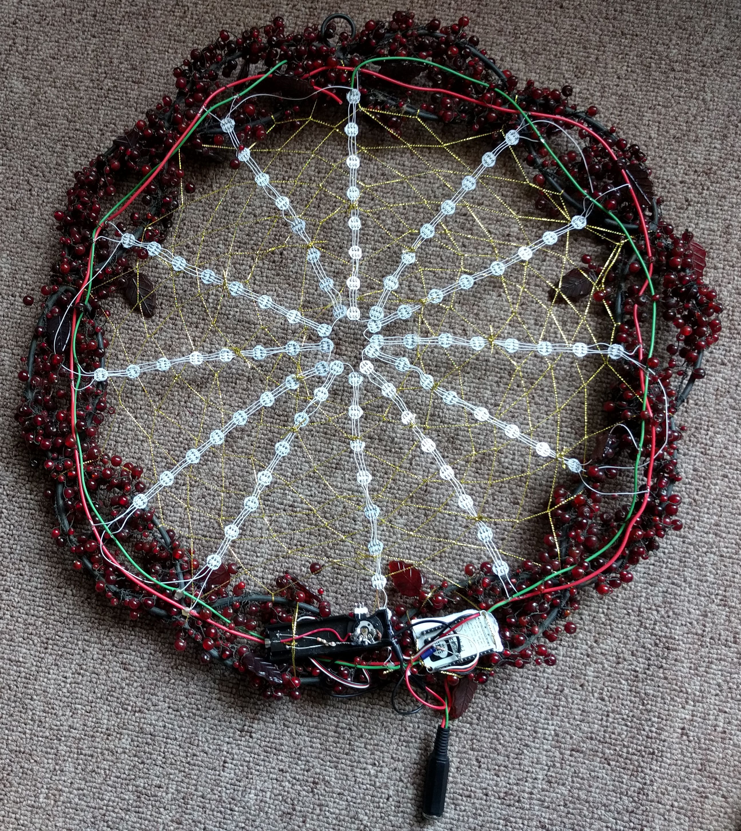
Here are some pictures of the completed display (Click for bigger)
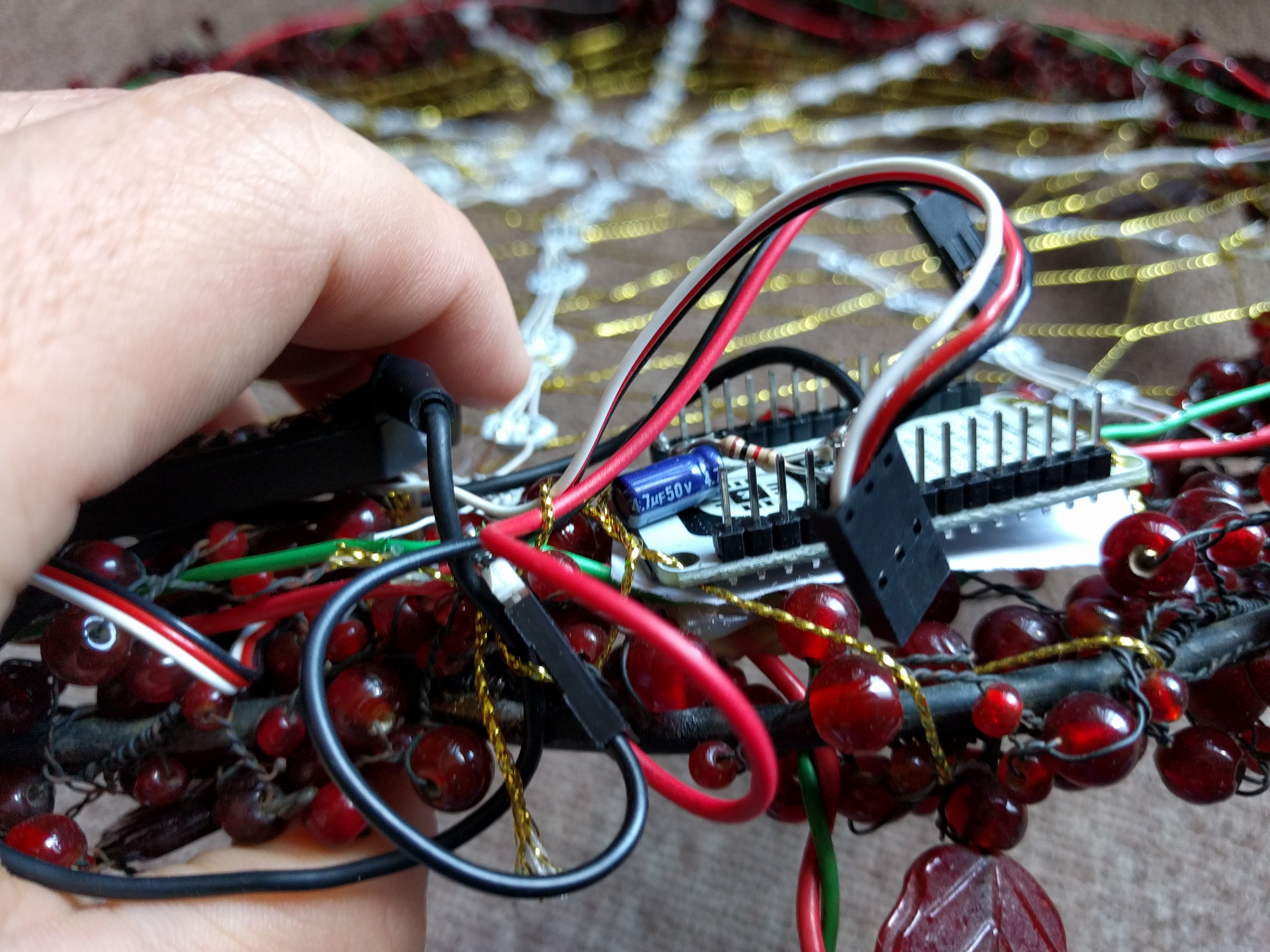
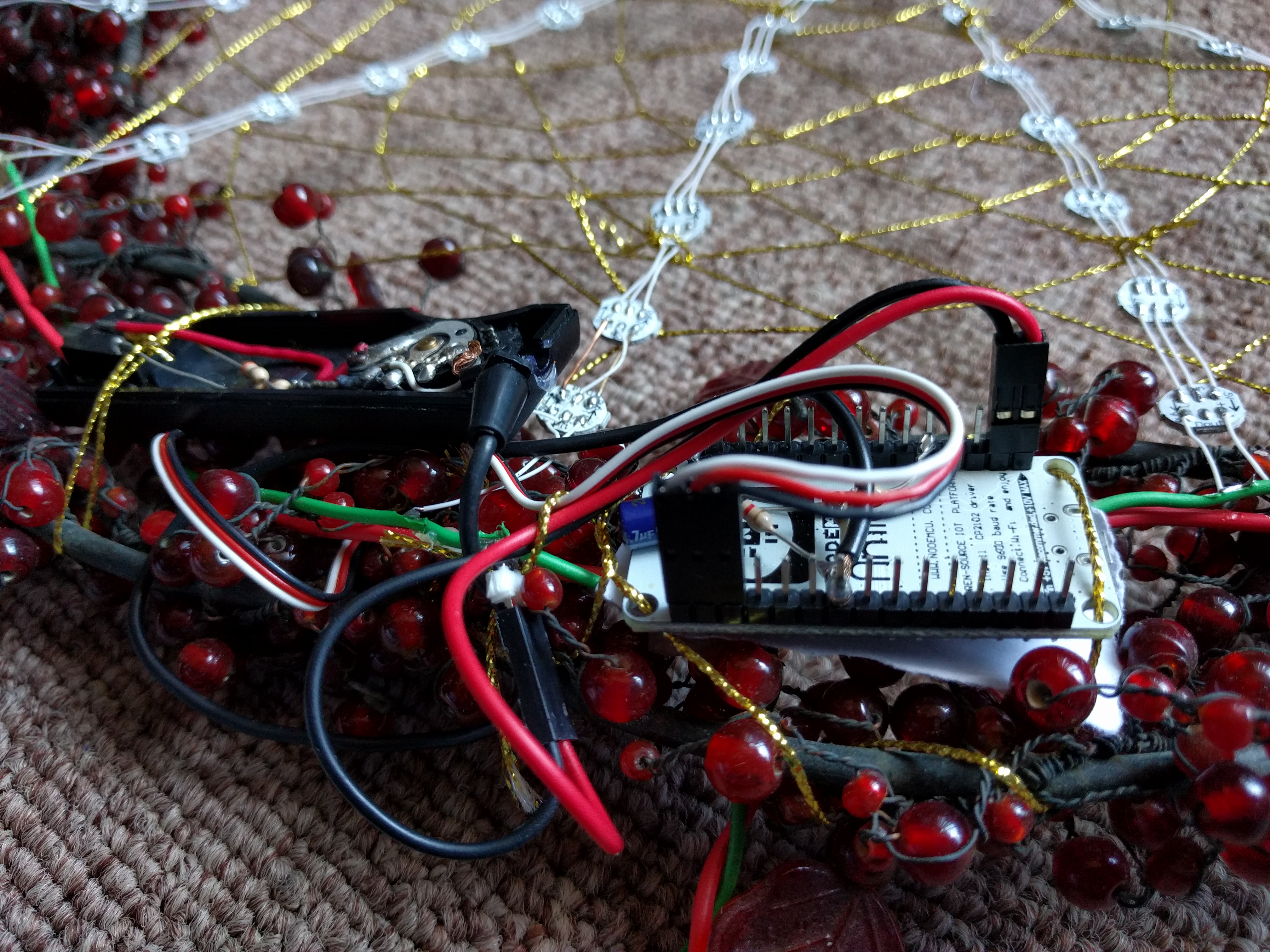
I later moved the circuitry to a dedicated board hanging below the display.
Software
Source code and scripts are available at: https://github.com/axlan/Sound-Catcher
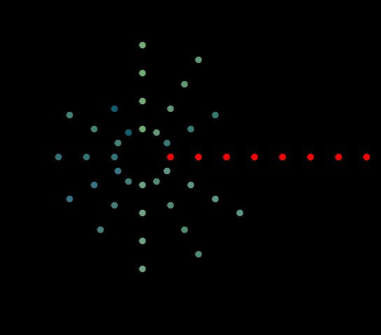
I initially started by testing algorithms and displays in octave and Javascript. I then wrote a few simulations of the LED patterns in Java. This code is also in the github repo.
Once I was comfortable with how I was going to process the sound and control the LEDs I started working on getting things up and running on the ESP8266. For simplicity I used the Arduino compiler and libraries where possible. However, I quickly hit some problems with the FFT libraries I found. The best one available http://wiki.openmusiclabs.com/wiki/ArduinoFFT and it’s more optimized version both used assembly instructions targeting an AVR MCU. I ended up finding two alternative libraries, but had to tweak both of them to account for the instruction set and compiler quirks.
I initially programmed it over the USB serial with the Arduino IDE, but I quickly switched to using Visual Studio Code along with a compile and upload script.
The upload script works with the example over the air update project in the Arduino library. The script relies on the GNU cURL usually found in Linux. I installed a version in windows to avoid needing to learn the equivalent tool in power shell. The WiFi uploads were actually faster then serial, though the reset process was a little time consuming.
To ease development I created a framework for making LED displays. They just needed to provide an update function. This allowed me to make a factory for initializing an arbitrary display based on name and have a standard interface for getting a list of configurable settings.
I divided the displays into categories and tried to figure out how to best divide the code to share functionality. I started with test patterns. Then I created a clock that kept time by querying an NTP server. With these worked out I went into the process of tuning the FFT displays I made previously to run on the HW.
Once I got the basic functionality working I made a web UI for selecting a display and customization options.
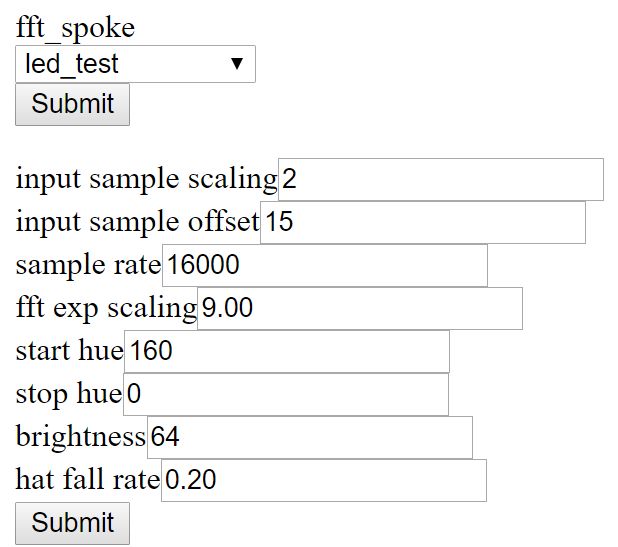
The UI was designed to require minimal boiler plate and ended up making my life much easier since I didn’t have to recompile as often when tweaking things during testing.
Possible future improvements
- Make dream catcher strings more visible (luminescence paint?)
- Refine displays
- Refine web UI
- Add offline timekeeping to clocks
- Add watch dog to reset if a display crashes