
Flower Calculator
I wanted to do another electrical project that focused on aesthetics. While looking at thrift stores for material for another project I saw some pieces that inspired me. I decided to make a calculator that would light up flowers as a value was computed.
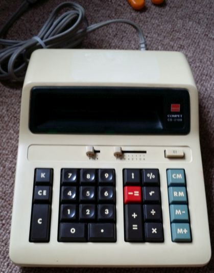
The two main ingredients for this project were an Easter basket and a wall socket powered calculator.
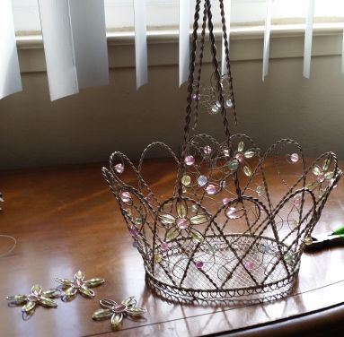
The basket was actually mainly bought to be turned into a crown, but I decided to reuse the handle and flowers for this project. Deconstructing the basket was mostly a matter of brute force. For the most part the pieces were weakly soldered together and could be pulled apart with pliers. I then did my own soldering to create a flower.
The electronics in the calculator were a bit harder to work with then I had initially anticipated. The board in the calculator is very simple:
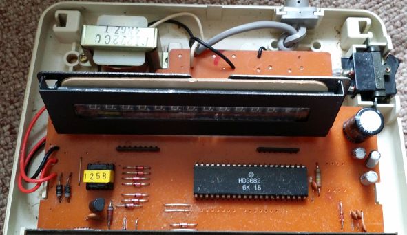
Though unfortunately, I wasn’t able to find any documentation for the board or for the chip. As I started to investigate the calculators inner workings. The whole circuit reminded quite a bit of the clock radio I had worked with on a previous project. Both used a variety of higher voltages, both were controlled by a single specialized IC, and both used relatively elaborate display control mechanisms to avoid needing to dedicate a pin to each segment of the display.
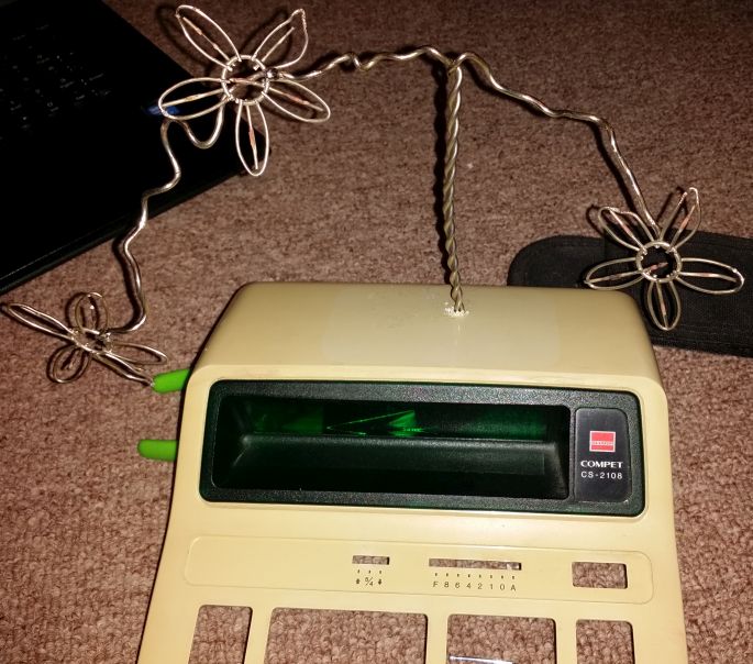
I decide to control the LEDs in the flowers based on the segments lit up in the display. The calculator uses a vacuum florescent display. The basic theory of operation for these displays is that there is a pin for each segment (for example, one of the two vertical lines that make up a one, or the decimal place) and a pin for each digit in the display (the ones place, the tens place etc.) The controller takes turns pulsing all of the segments for each digit and coordinates the pulses so that the right segments are lit up for each digit.
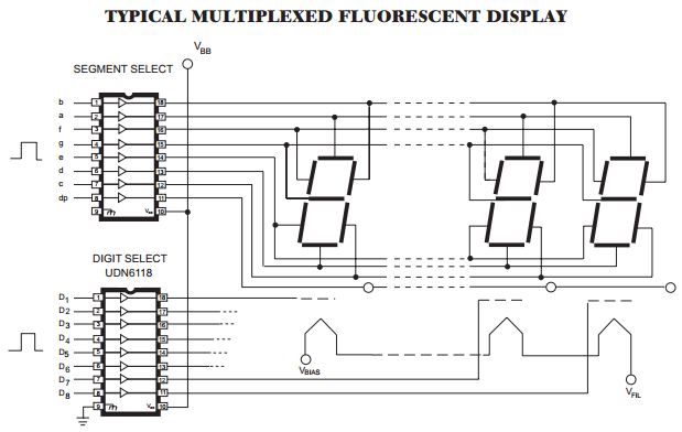
I figured out what I needed to know through a combination of poking around with an oscilloscope and reading data sheets for other displays. I found that the display had 13 pins that controlled digits and 10 pins that controlled segments. This was a little confusing since there were only 12 digits which each had 9 segments (the 7 segments for the numbers plus a segment for a decimal place and degree symbol). This discrepancy was caused by some error status segments. Below is a a capture from the oscilloscope of the pulse for one of the digits
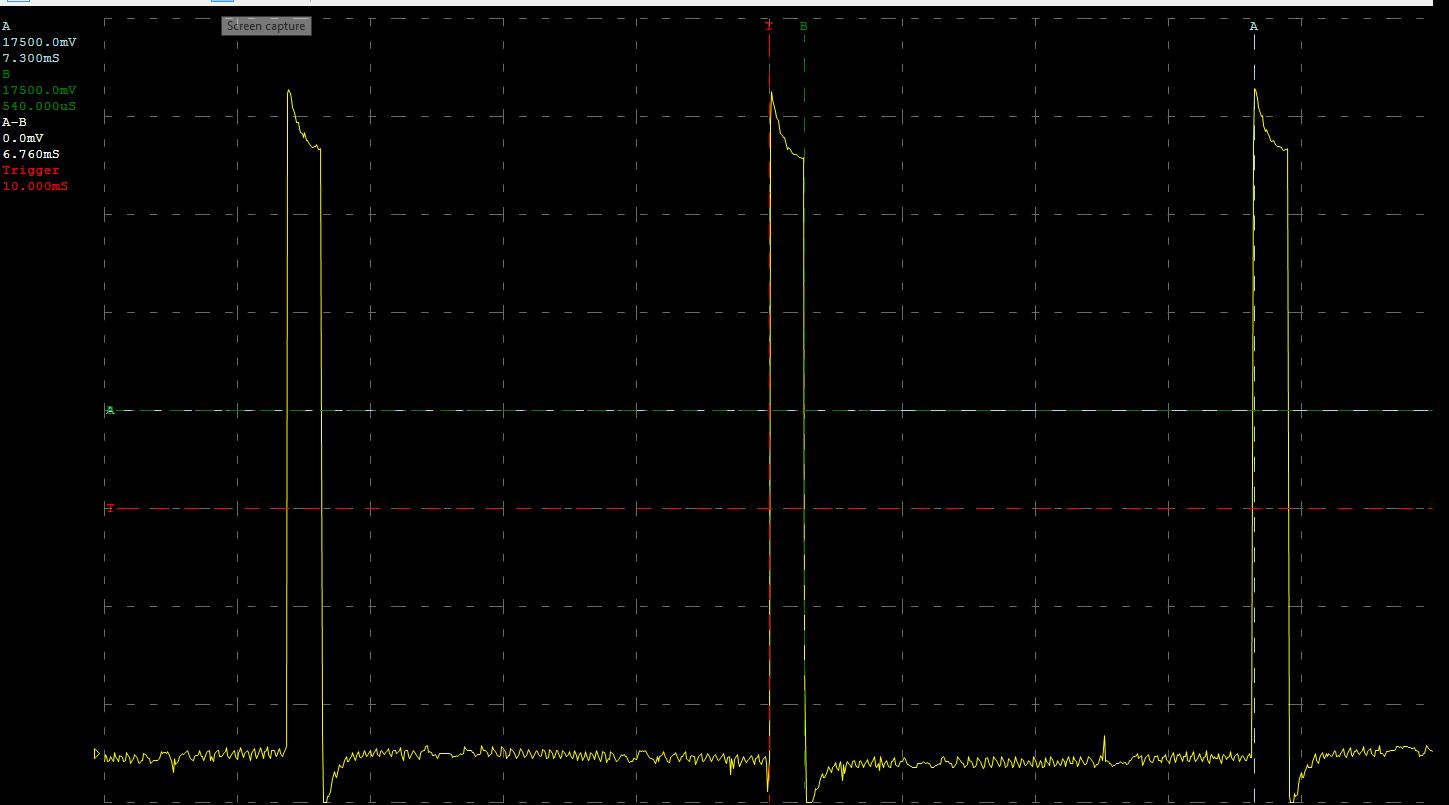
By looking at the spacing between the pulses I could see how often a digit is refreshed and how long the display is driven. This shows that effectively each digit is unpowered for 12/13 of the time and updated at about 137Hz.
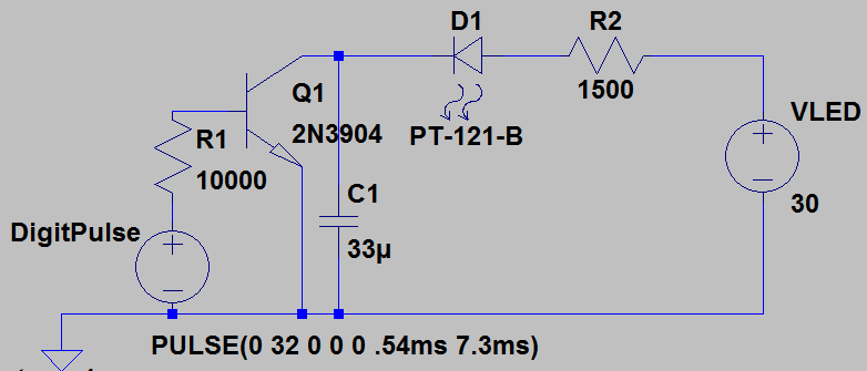
I decided to make the LEDs in the flower light up as larger digits were used on the calculator. I wanted to use some LEDs that I had recovered from a Christmas decoration. These LEDs have red, green, and blue elements, along with a control circuit. They cycle through different patterns and mix together the colors. The problem is that they needed to be continuously powered. They could not be pulsed like regular LEDs. Also since I did not know how much current the driver for the display could produce I decided to minimize my current draw by using transistors to drive the LEDs. Since it’s been awhile since I had designed a circuit like this I decided to use a circuit simulator. Specifically, I went with LTSpice. I have yet to find a spice simulator with an easy to use interface, but I was able to get a circuit working:
Here you can see the simulation result. The green is the simulated pulses coming from the display driver, and the red is the current going through the LED.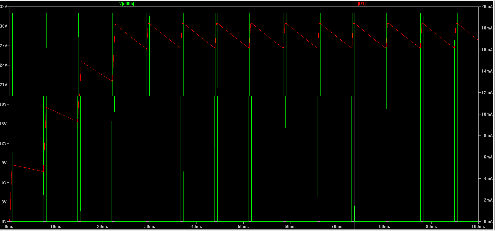
One thing I haven’t mentioned was that the OV in the simulation seemed to correspond to -30V for the actual calculator. This seems typical for these displays, but it made deciding which points in the board to use as reference or to power things a bit confusing.
I then went and tested this circuit out:
I demonstrate that removing the capacitor causes the controlled to repeatedly reset due to the pulsing from the digit driver.