Web Based Door Control
After have locked myself out of my apartment one too many times, I decided that running to make a keyless entry system. I’ve been looking for a project to use a Raspberry Pi in for awhile, and this seemed like a good fit.
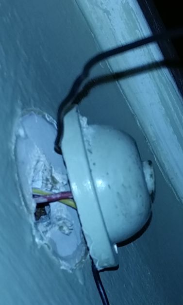
The basic set up was pretty straight forward. My apartment had a buzzer, so I wanted to be able to switch on the Buzzer through my LAN.
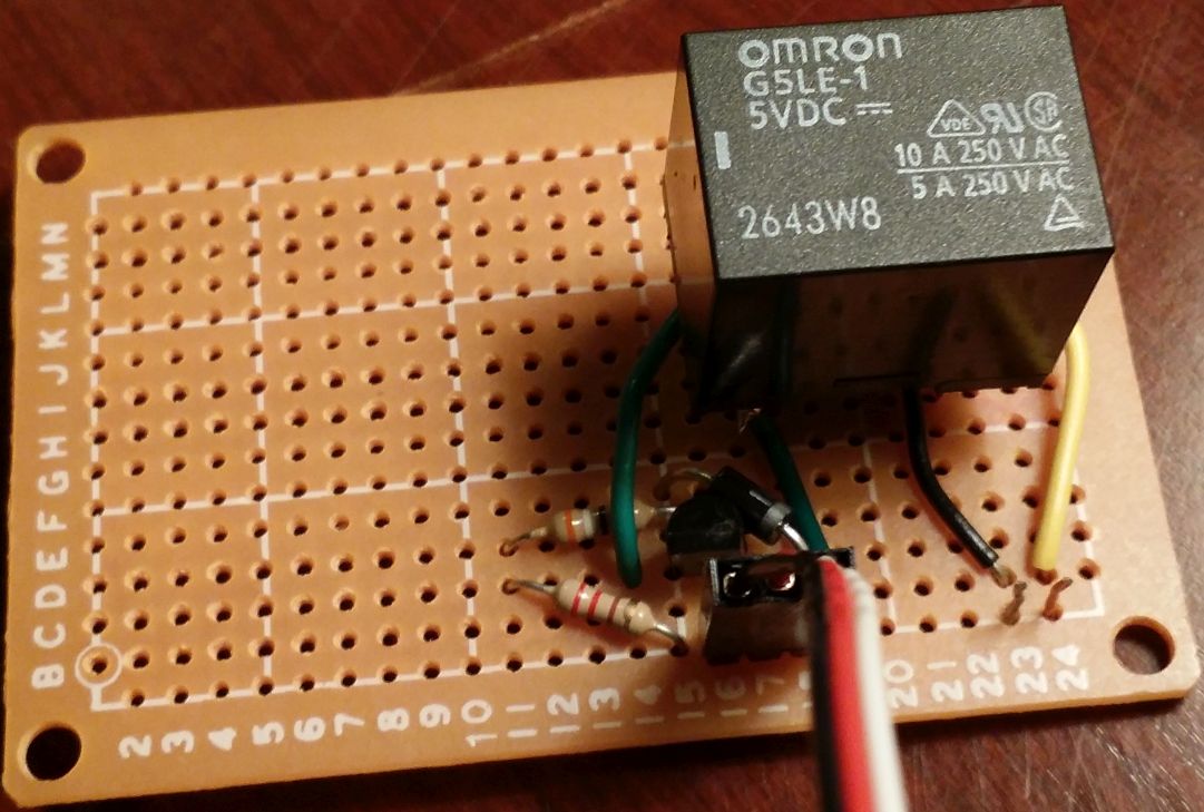
Since the buzzer is medium voltage AC, I decided to use a relay as the switch. I went with a g5le-1-g dc5 . The important stats were that it supported the voltage and current my buzzer used, and that the coil was 5V and draws about 80 mA. Unfortunately, the GPIO pins on the Raspberry Pi are 3.3V and can only output a max of about 16mA. This meant that I needed to use a transistor to drive the relay. I had a bunch of 2N4401 lying around, so that’s what I used. I used this circuit:

Details on this circuit can be found here http://pcbheaven.com/wikipages/Transistor_Circuits/
The basic theory of this circuit is that a small current will go from the input through the base of the transistor and out the emitter to ground. This current allows a much larger current to flow from the transistors collector to ground, driving the coil of the relay. Rb should be chosen so that the current coming from the input is within the Raspberry Pi’s GPIO spec, but the amplified current going through the coil can still close the relay.
Since the gain of the transistor hfe is at least 20, I just needed a current through the base of 4mA. This meant that I needed an Rb between 637 and 160 Ohms. I got these numbers from (input_voltage-Base-Emitter_Saturation_Voltage)/(base_emiter_current) . For the max resistance this became (3.3V-.75V)/4mA=637.5 ohms
Initially I tested this out on a breadboard and confirmed that the relay closed when I connect the input to 3.3V (or 5V for that matter.
I then soldered the circuit together onto a protoboard
I happened to have some nice jumper cables that I used to connect this board to the Raspberry Pi.
As I was getting the hardware working, a friend of my was over and helped out by working on the software.
To control the GPIO pins he followed the guide found here https://projects.drogon.net/raspberry-pi/gpio-examples/tux-crossing/gpio-examples-1-a-single-led/ . Basically he installed wiringPi to provide the control interface. To figure out what pins on the header to use, we looked at http://wiringpi.com/pins/ . Since we needed 5V, GND, and a GPIO pin we chose pins 4, 6, and 8 so we could directly connect a 3 pin jumper. It is important to note that the GPIO pin (pin 8 on the header) is named pin 15 in wiringPi.
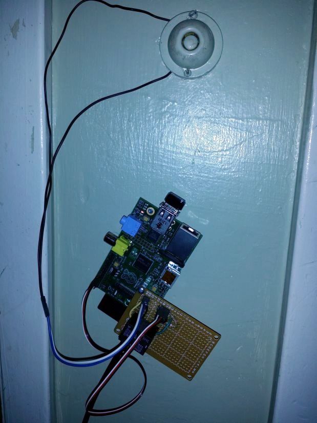
At this point we were able to confirm that the Raspberry Pi was able to control the relay when connected to the circuit. We mounted the protoboard to the Raspberry Pi board with a spacer and Connected the whole thing to my buzzer.
To do this I added some extra wires to the buzzer and connected them to the relay.
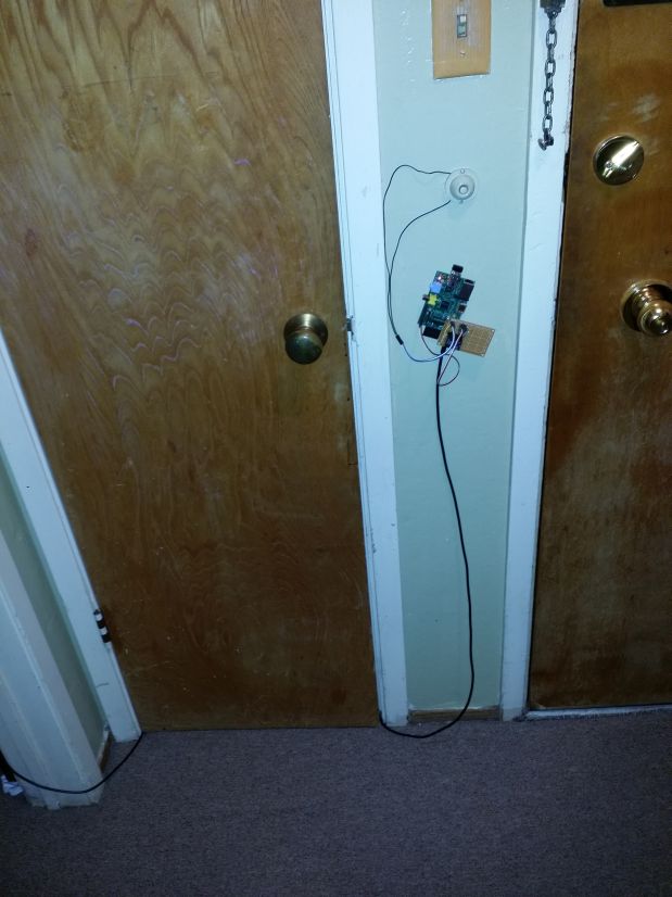
I had bought a 10ft USB micro connector to power the Raspberry Pi, and was able to test the the whole system was working. I hit a minor snag since I didn’t have a good way to mount the boards, so you can see that the whole thing is hanging on the wall by a nail.
Lastly my friend worked on setting up the relay to be able to be controlled through the LAN. I had purchased a small WiFi dongle for the board, so it was already connected to my network. He set up apache and wrote a simple perl script to trigger the relay.
#!/usr/bin/perl

$| = 1;
print "Content-type: text/plain\n\n";

`gpio mode 15 out`;
`gpio write 15 on`;
print "door activated\n";
sleep(10);
`gpio write 15 off`;
print "door deactivated\n";
With the script saved in /usr/lib/cgi-bin/ I just needed to connect to my LAN and go to the right URL for the door to open for 10 seconds. We could have also done the whole thing by making a Python servlet, or any number of other ways, but this was quick and easy.
Since the URL would only be available from my LAN there is at least a minimum level of security. Though I would probably want to add some authentication if I ever wanted to make the Raspberry Pi’s web server accessible over the internet.
Now if I forget/grab the wrong keys I can get back in with my phone, or in the worst case I can find someone to help me unlock the door without needing to resort to a lock smith.
Update:
I realized that it is super easy to trigger the door unlock from my Pebble watch. I simply followed the guide posted here http://conoroneill.net/pebble-controlled-electric-blanket-using-cloud-pebble-simply-js and in about 10 minutes I was able to create an app for my watch that could open my door.
Future features:
- Detect doorbell, either electrically or with a microphone
- Unlock from SMS. It seems like setting up a number with https://www.twilio.com/ would make this pretty easy
- Security features, I could get a notification when the door opens, or add a webcam to the Pi
- Clean up install. Add a case and mount things more securely
- Add authentication for the web page
Update from the future:
I ended up simplifying this a bit by switching from a rasb Pi to an ESP2866:
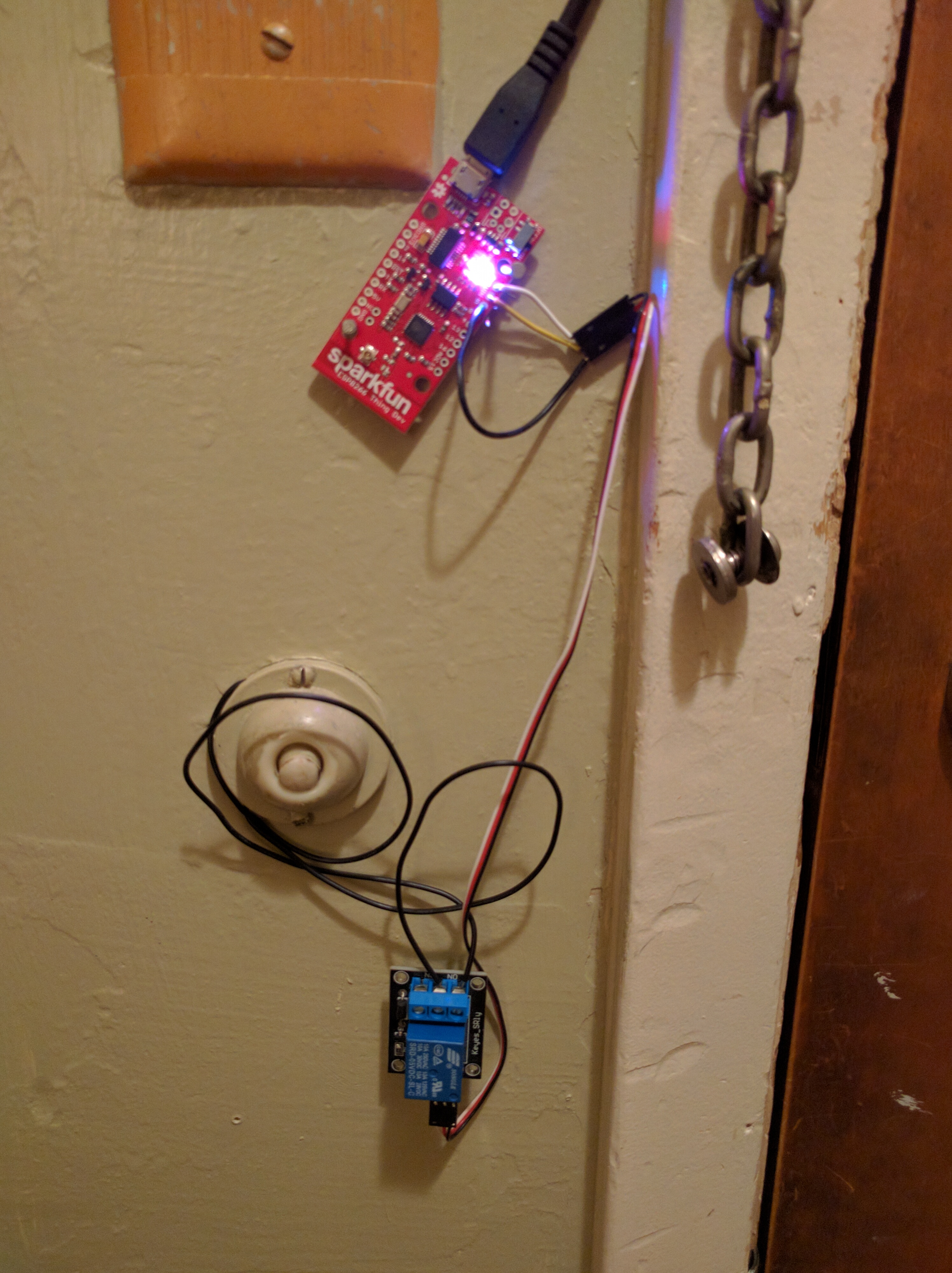 I got a breakout board for the ESP2866 and the relay off amazon and used the ESP2866 arduino bootloader and libraries. Cheaper, simpler, and lower power.
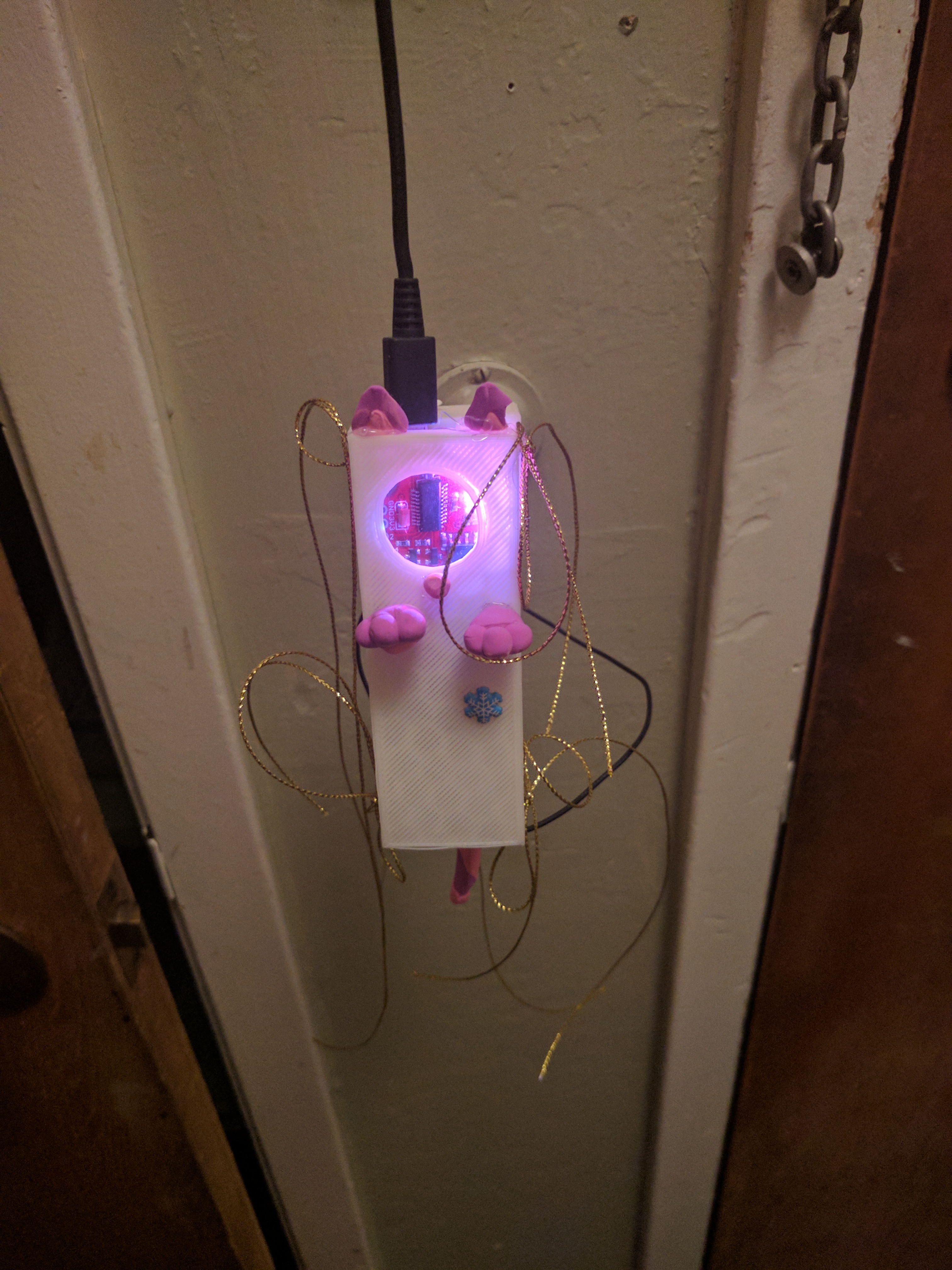
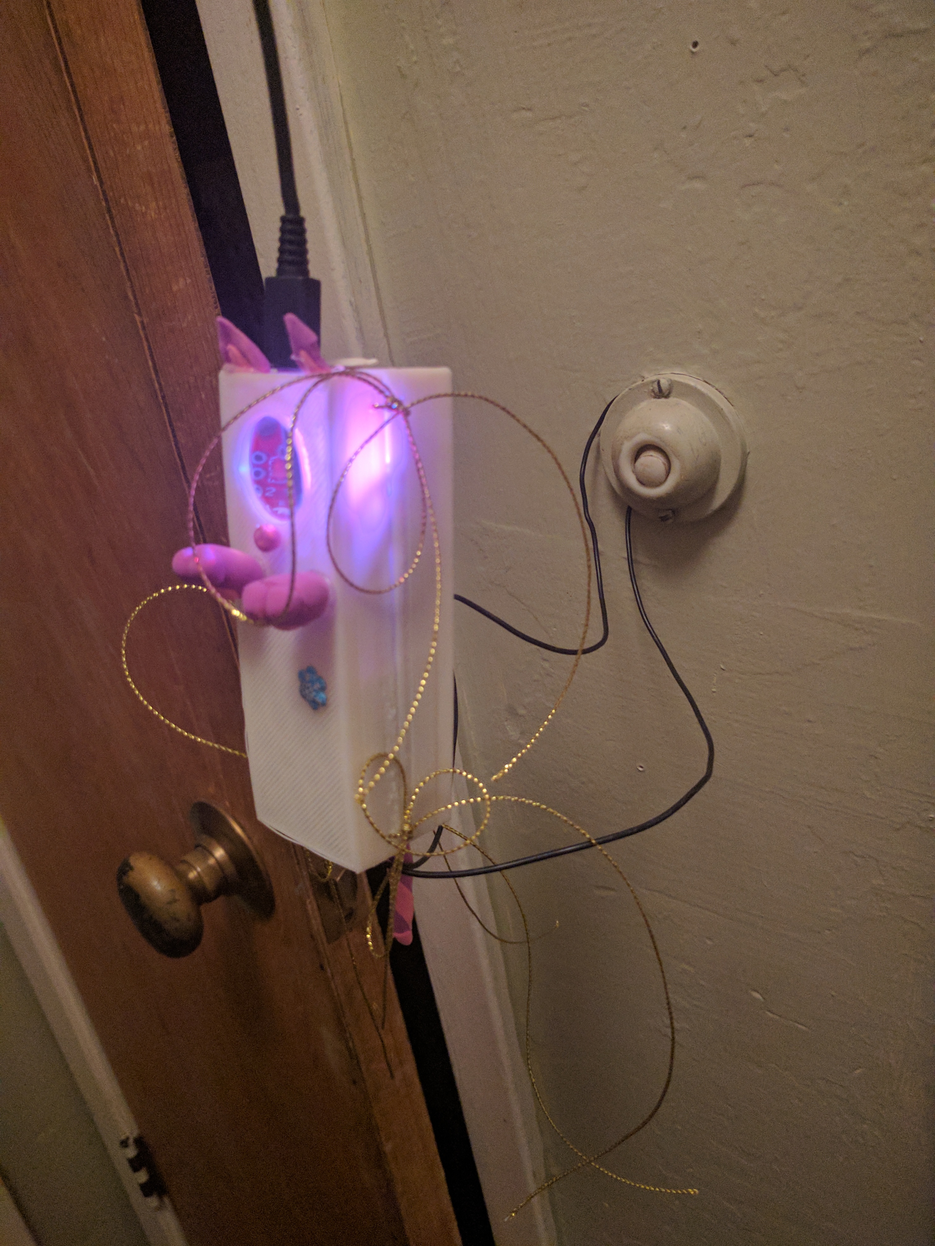
Later Maria made a 3D printed enclosure:
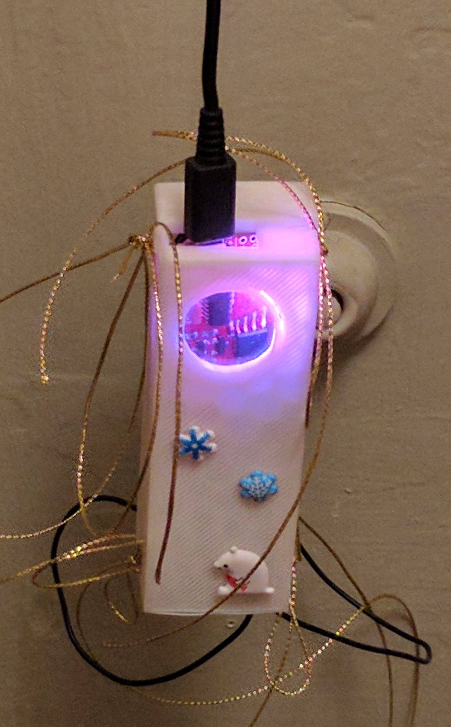
and further decorated it with some clay