
Laser Stars
This is a bit of a weird one. I’m not sure what drew me to this project, but I decided to do a project to use a laser to draw “constellations” on some glow in the dark stars on a ceiling. I wasn’t sure how complex the control software would need to be, so I ended up biting off a bigger project then I initially intended. In the end this was less about result, and more about the challenges that this system posed.
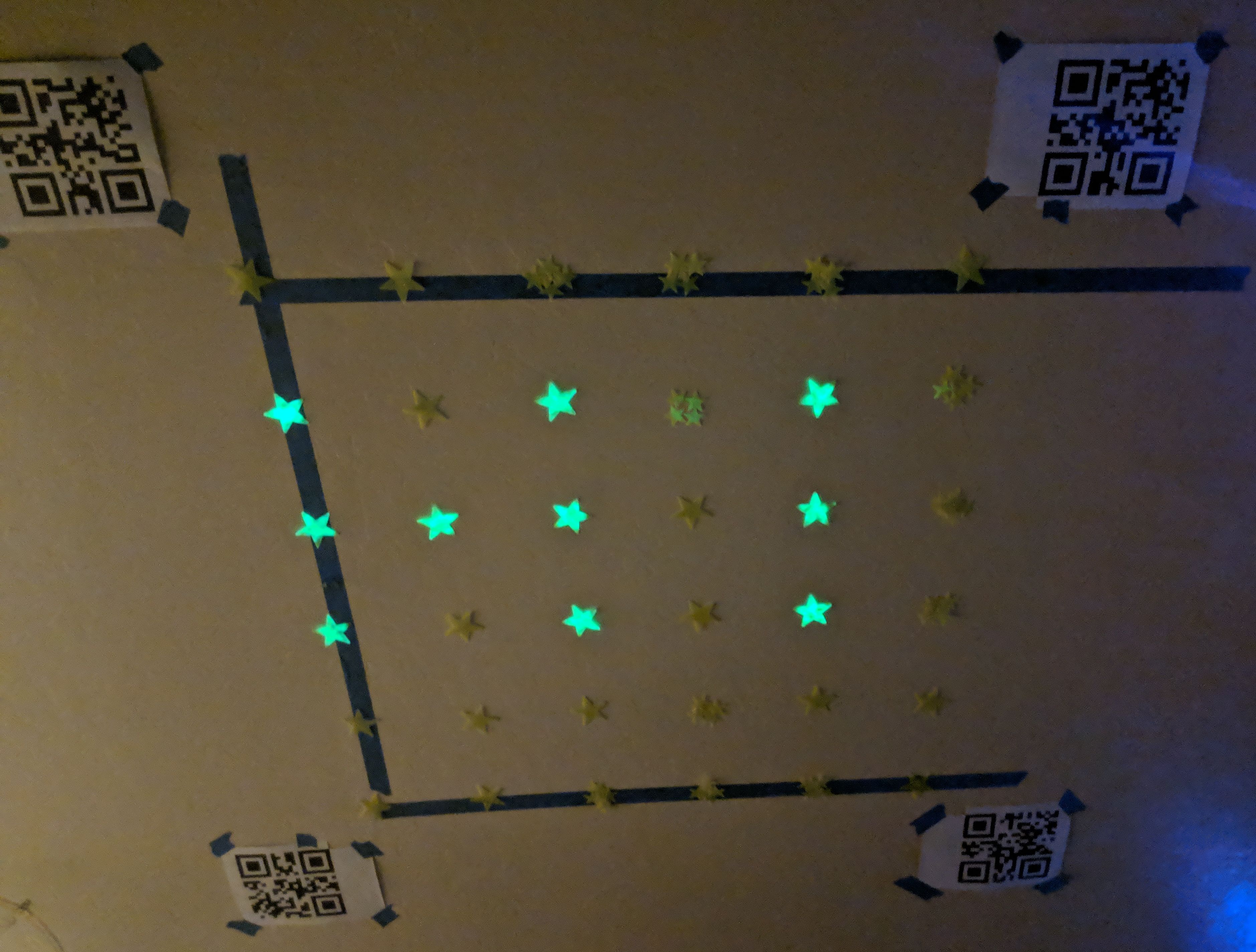
Note that this wasn’t drawn by the control system I’ll talk about, I drew this by moving the laser manually.
Hardware
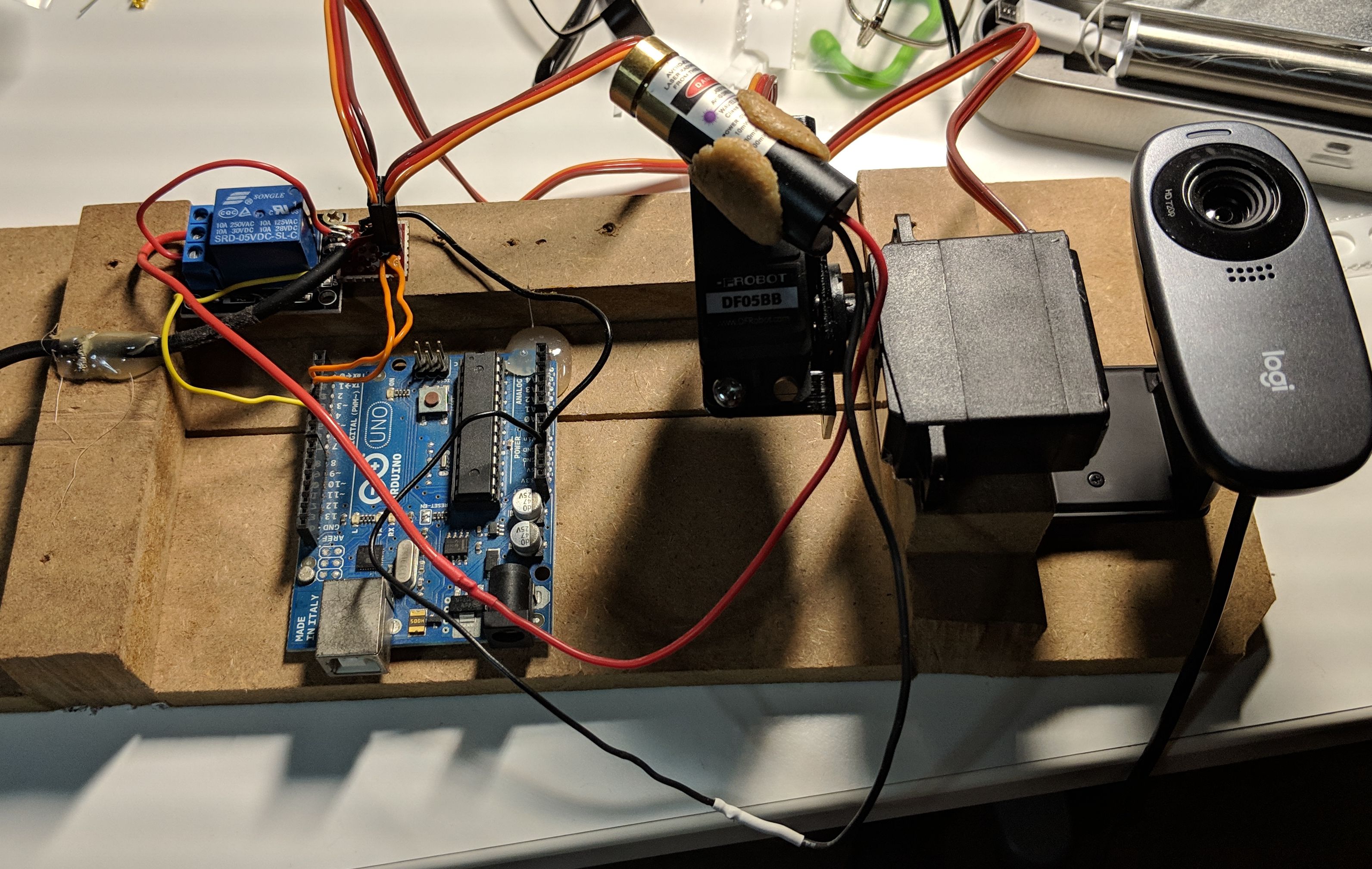
The hardware for this project was pretty straight forward. I got a tilt/pan kit, a violet laser, and a relay module. I used an Arduino I had lying around, along with some other scraps.
Initially I used a lower power red laser to lower the risk of eye damage, and I also used laser protection goggles.
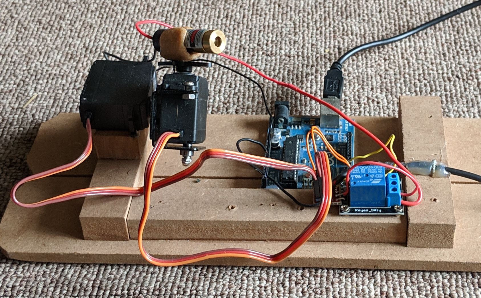
Here’s some pictures of the initial test set up:
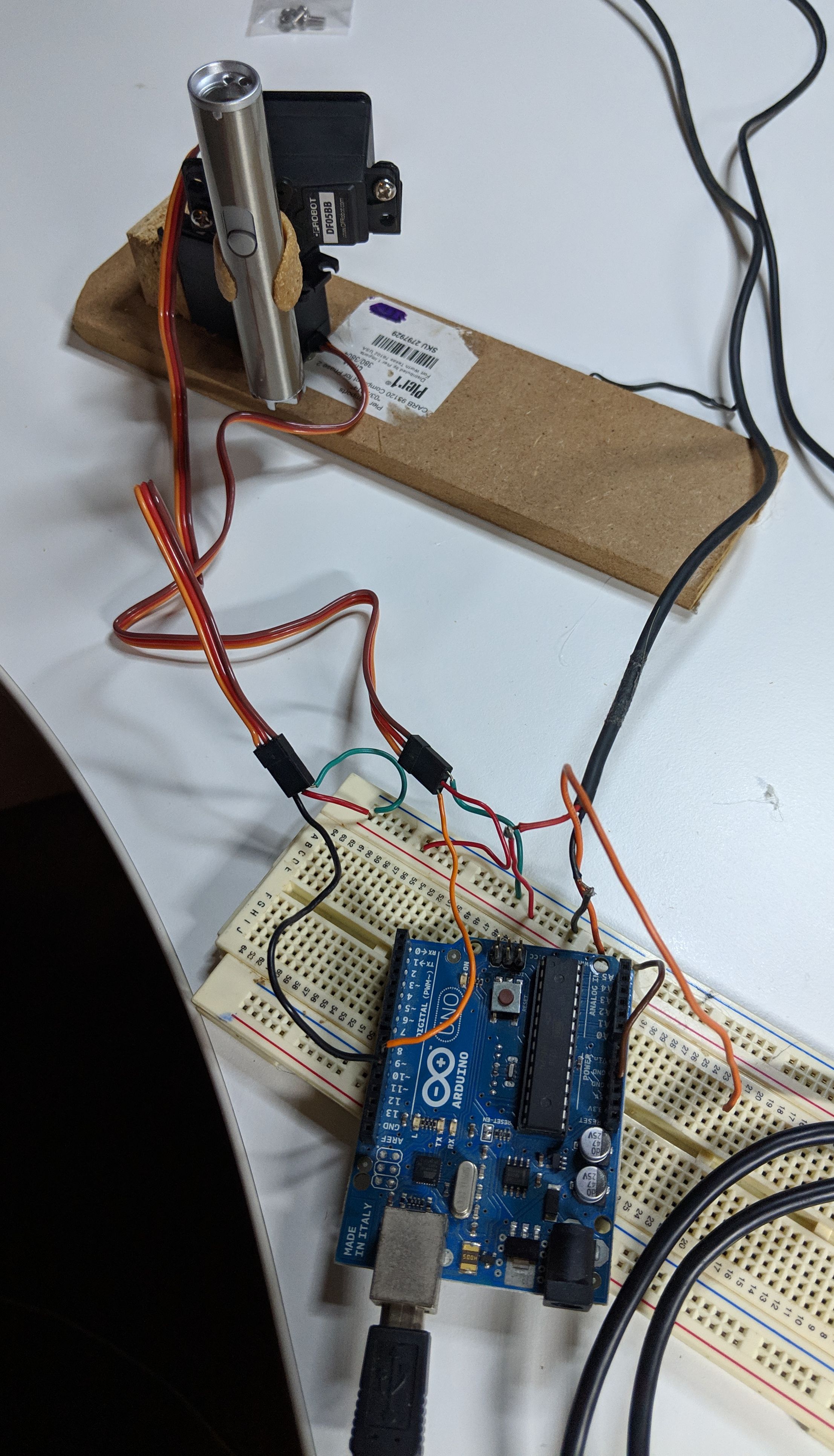
I used a small amount of warbla to create the mount for the laser.
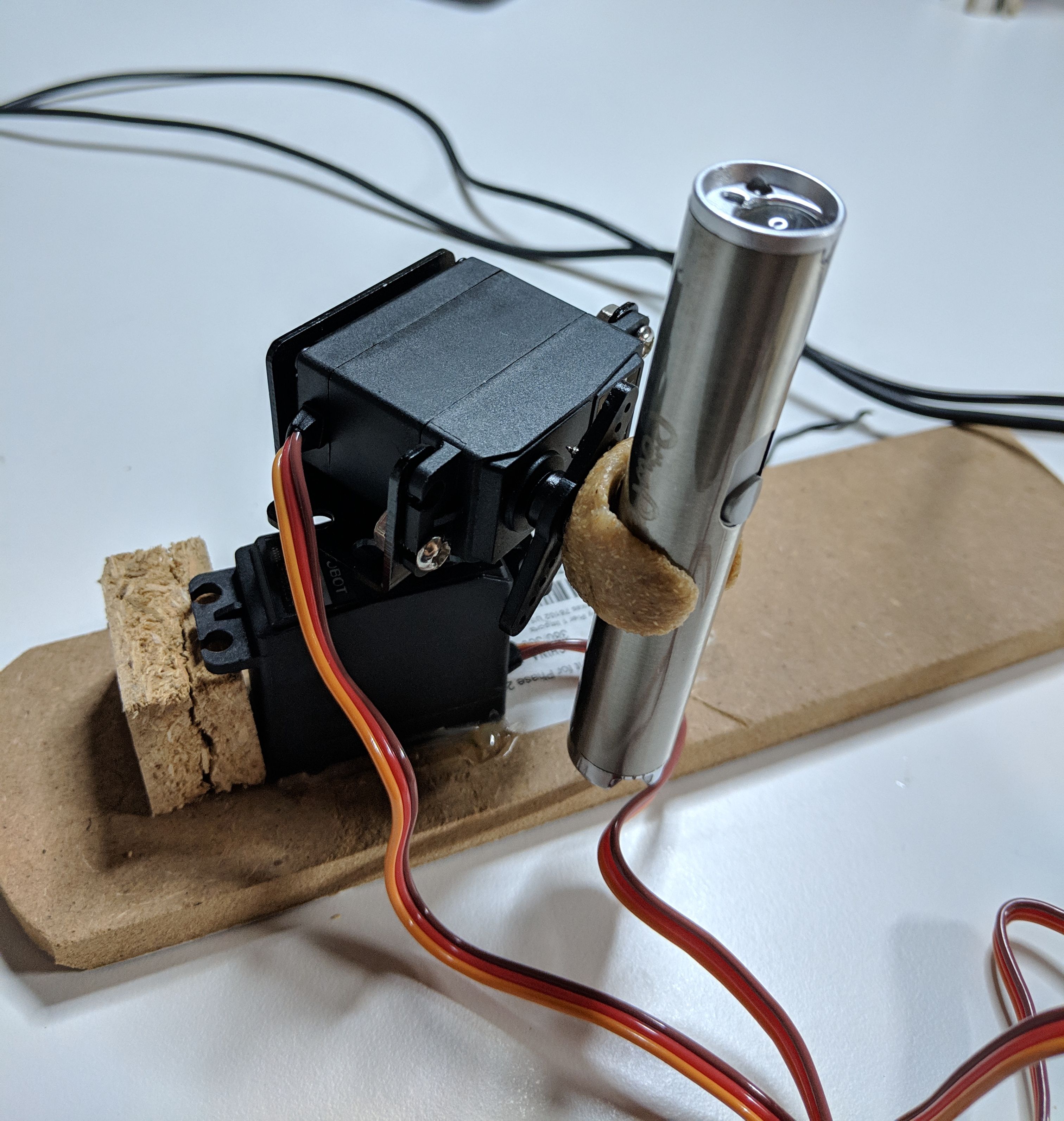
To make things stable enough to test, I mounted everything on a piece of wood.
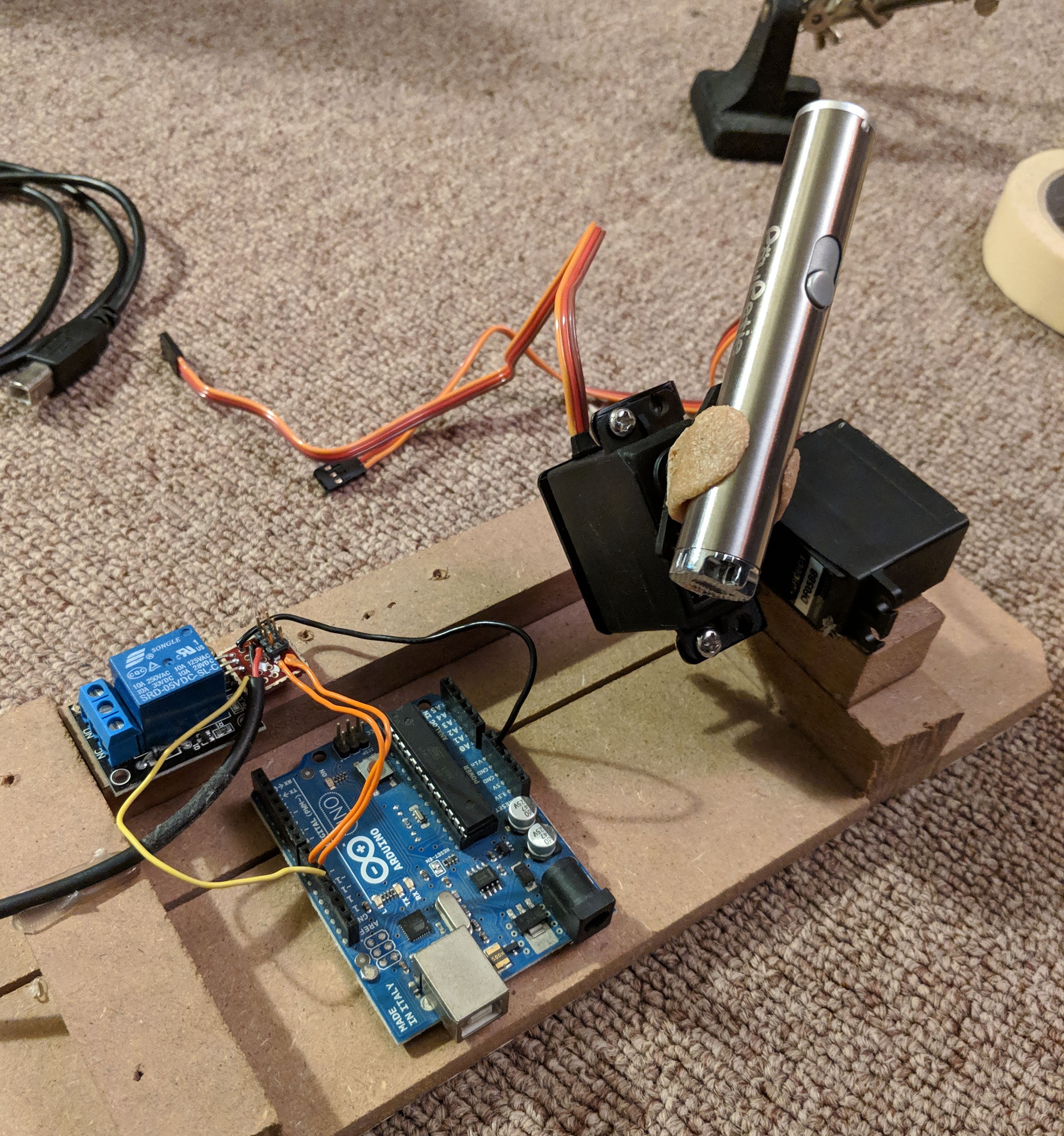
Here’s what it looked like with the violet laser mounted in:
Software
The code for this project is hosted on Github: https://github.com/axlan/laser_stars
Arduino
I started off with a very basic driver for the Arduino. For simplicities sake I decided that the Arduino code would be minimal, and just take raw commands for setting the servo positions, and relay state https://github.com/axlan/laser_stars/blob/master/laser_firmware/laser_firmware.ino. This didn’t really change much from the initial implementation. Really the only change was to go from using write which has a resolution of a degree to writeMicroseconds to get higher resolution control of the servos.
Utilities
As I was working on the project I made a couple helper utilities.
-
Line Drawer - This was a graphical interface for drawing an image that could be translated into laser movements.
-
Tracker Calibration - When I started working on detecting the laser in OpenCV, this was useful for figuring out the thresholds.
-
Manual Control - This was used to test the Arduino firmware and get a rough calibration of the values.
Control Software
Movement Instructions
The first thing I did was make a simple scripting language to encode the laser movements. It looks like:
1
2
3
4
5
6
7
SetPower False
MoveTo 0.48 0.2425 0.1
SetPower True
Wait 3.0
MoveTo 0.37375 0.05875 0.1
MoveTo 0.1975 0.035 0.1
...
There are 3 commands:
- SetPower - turn the laser on or off
- MoveTo - Movement is from x=0,y=0 to x=1,y=1 scaled to drawing space. Velocity is in same units / second.
- Wait - seconds to wait at the current position
Run Controller
I then set up a framework that would let me load a configuration set from a JSON file and connect a driver, controller, and analysis modules. I spent a lot of time getting a simulator to work, to make developing faster and more comfortable then dealing with live hardware.
Initially I was hoping to just calibrate the servos and draw without any sort of feedback loop. However, I realized I wasn’t going to have enough stars to make this look particularly good, and getting everything lined up would be very tedious.
I ended up using OpenCV to both track the laser, and localize the camera view. For localizing the camera view, I didn’t wanted to go with something simple, so I taped QR codes measured out to bound the part of the ceiling I would be drawing on. All the OpenCV work was based on other projects.
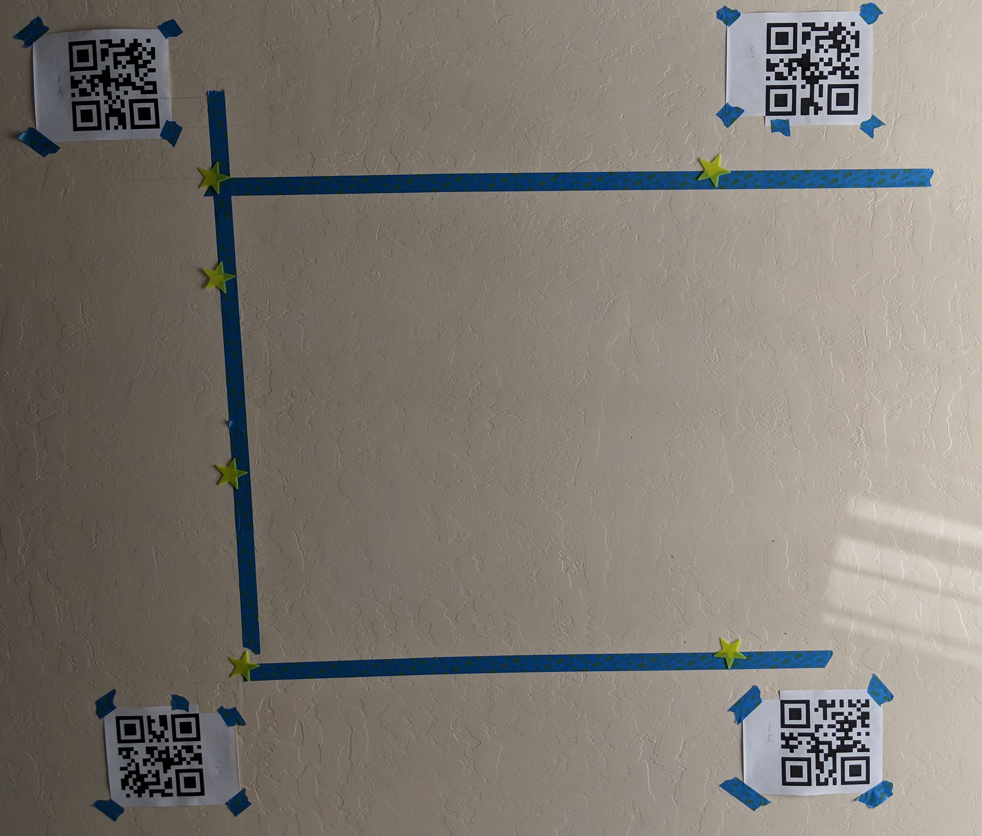
Once these were up, I was able to add an analysis module that would superimpose where the stars should go, to help guide me as I was taping them to the ceiling.
The stand alone webcam I had actually didn’t have a wide enough field of view, so I ended up using my phone as an IP webcam using this app IP Webcam. I was very happy to find how seamlessly OpenCV could deal with attached cameras, video files, or IP cameras without needing any real change to the underlying code.
What I ended up with, was using the combination of QR code localization and laser tracking to do an initial calibration at startup. This could be save to avoid rerunning it every time. However even though this worked pretty well, there was enough error in the motors movements, that a single calibration at startup wasn’t enough.
Here’s a video of the laser in action:
And a recording from the perspective of the control software. The controller was trying to run across each of the rows of stars. Note that the QR codes let the view snap and scale to the target area.
Future improvements
If I just added a high density of stars, or even used glow in the dark paint, I think my current set up would be more then adequate to get some neat looking results.
If I wanted to get the control system to where it could get better then an inch accuracy, I’d probably need to add a continuous feedback loop. I realized as I was designing this system, that I ended up implementing a very primitive version of the robotic operating system (ROS). If I wanted to keep going, it would probably make more sense to move to a system like that to give a better platform for developing a PID controller, or Kalman filter.
Reference Projects
https://github.com/AnumSheraz/OpenCV-laser-tracking-gun
https://github.com/bradmontgomery/python-laser-tracker
Localization with QR codes:
http://www.geduino.org/site/archives/258
https://www.learnopencv.com/barcode-and-qr-code-scanner-using-zbar-and-opencv/
https://www.pyimagesearch.com/2014/08/25/4-point-opencv-getperspective-transform-example/