Outlaw Star Gillium II Clock
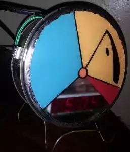
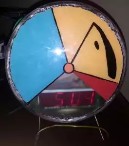
My brother and I used to watch the anime Outlaw Star together as kids, so I decided to get him something based on the show as a gift this year. Being a relatively unpopular show that hasn’t been on the air in years, there was basically no merchandise available. So I decided to make my own. This is a clock made to look like the computer Gillium II from the show.
Parts list:
- Fruit Cake Tin – Any round tin would work for the enclosure, I got this one from the thrift store for 50 cents
- Clock Radio – Something that is reasonably close to being able to fit in the tin. I also got mine from the thrift store for $3
- Piece of Plastic – I bought a 11″x14″ piece from home depot, for $4 making this the most expensive component
Next I dissected the clock radio. Originally I was hoping to drive some blinking lights with some of the clocks circuitry, but it turns out that the clock that I found used a fairly interesting scheme for controlling the LEDs. The clock chip was a lm8560. The AC power coming in goes through a transformer which steps the voltage down to 20V peak-to-peak. As the power oscillates from +10 to -10 the controller switches which segments of the display are being powered. In any case I decided that I would leave well enough alone and concentrate on fitting the circuit into the tin.
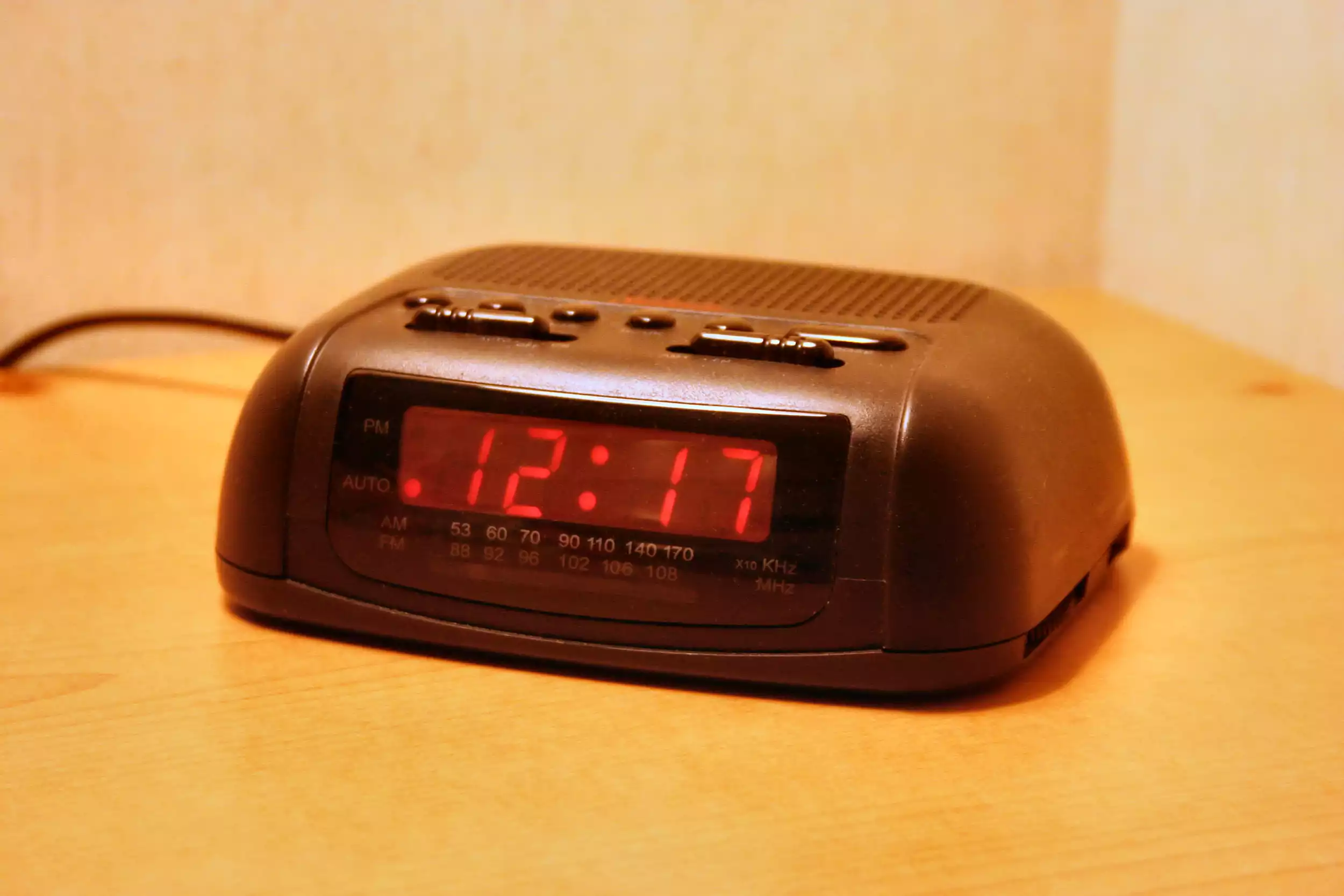
The clock radio I used looked like this
In order to fit the board into the tin I needed to rotate the display 90 degrees so that it faced upward. This meant that there was no way that I could reuse the original set of controls. I didn’t feel the need to preserve all of the radio and alarm functionality so I decided to make the only input the time setting controls.
First I removed a four position switch that was used to change the alarm/radio mode and hard wired the connections to the position that disabled the alarm. Next I spent some time figuring out how the buttons on the original panned were used to set the time. This clock had the scheme where you hold down a “time” button and then press a minute or hour button. Turns out the time button just connected the hour and minute buttons to their common ground. I ended up wiring the switch so it would switch between no connections, and connecting the minute and hour inputs to ground so you could get the original controls but in switch form.
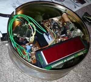
Before I mounted the clock circuit into the tin I desoldered some of the extra parts like the speaker and the original input circuitry. The clock circuit was just barely to big to fit, so I had to cut off some of the corners which fortunately didn’t contain anything important. I screwed the clock circuit back onto the plastic bottom of the clock which I cut down to a size that would fit. To put everything together I had to I ended up gluing the switch, cables, and circuitry in place with epoxy. I cut a little chunk out of the tin for the cable to fit through and bent back the metal so the cord wouldn’t be sitting on a sharp edge. With all the done the tins lid could still be taken off and on giving access to the inner side of the plastic and the clock circuitry.
I painted the colored parts of the clock face on the inside of the plastic, and doing the black sections on the outside with a sharpy. I’m sure there’s a better way since the paint I used could be easily be chipped off if it rubbed against anything sharp, but still it ended up looking pretty nice.


