
Tearing Down a Digital Ovulation Tester
In starting to try to have a baby, my wife got a digital device to track her hormones. Who am I to turn down an opportunity to reverse engineer something?
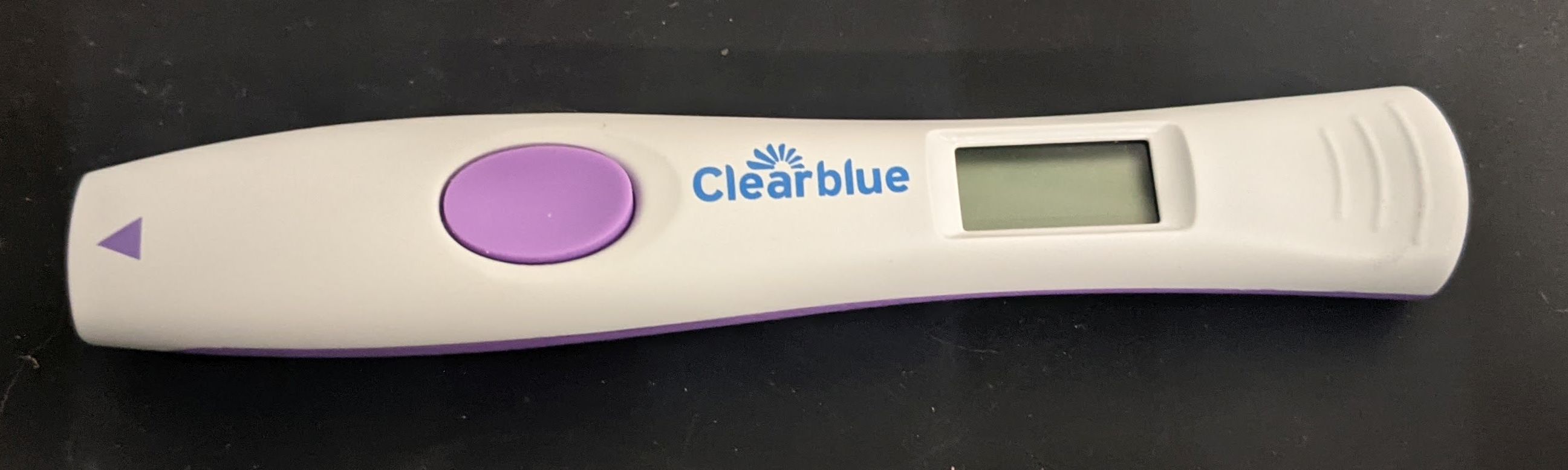
This device is extremely simple, which makes it an interesting example for how a consumer medical device like this is designed. It works similarly to a pregnancy test. The device comes with cartridges which are just paper treated to develope colored bands in the presence of certain hormones.

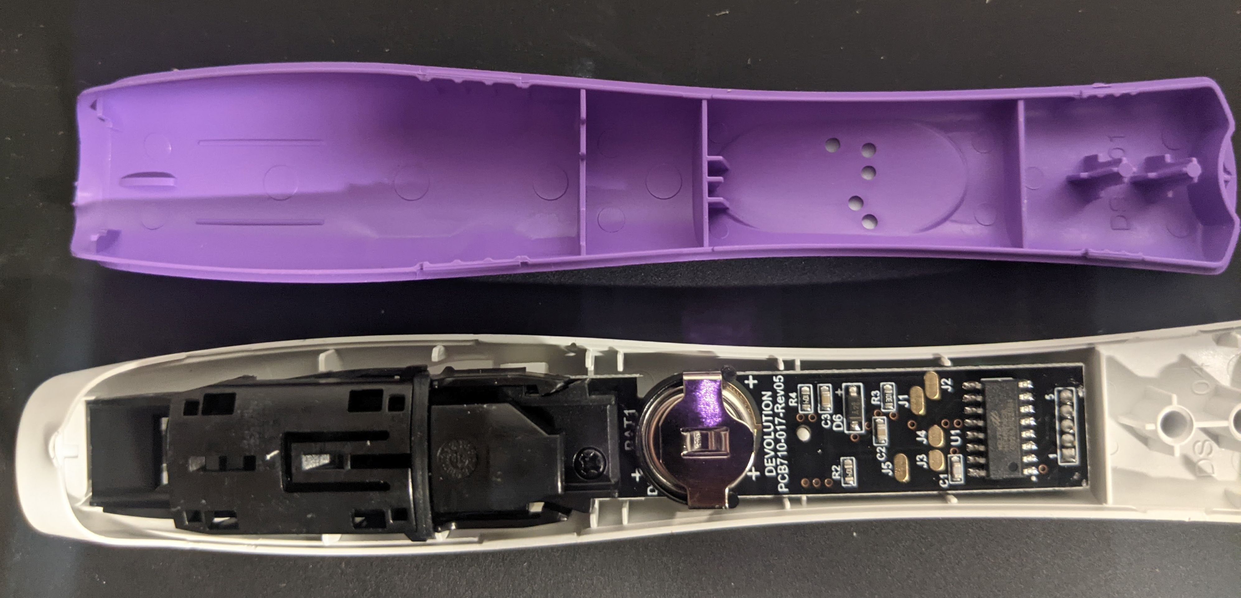
The device shines LEDs on the stick and reads off the reflected light from 2 detectors with a microcontroller. The microcontroller then updates the LCD with the results. Aside from a few passive components the only other parts are a user button, and a button triggered by inserting the cartridges.
The teardown itself was fairly straightforward. Here it is in one piece for the last time.
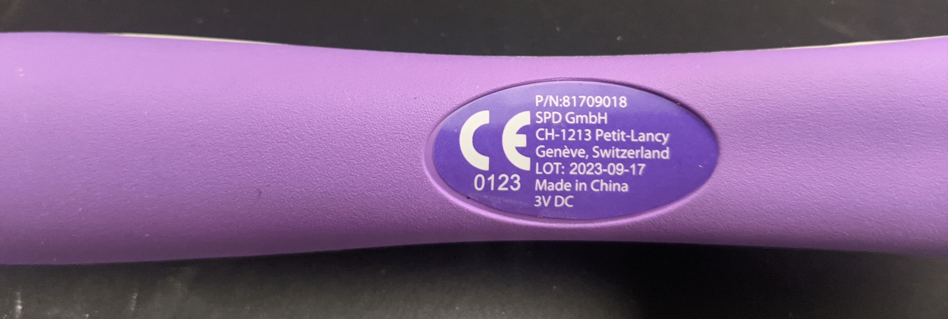
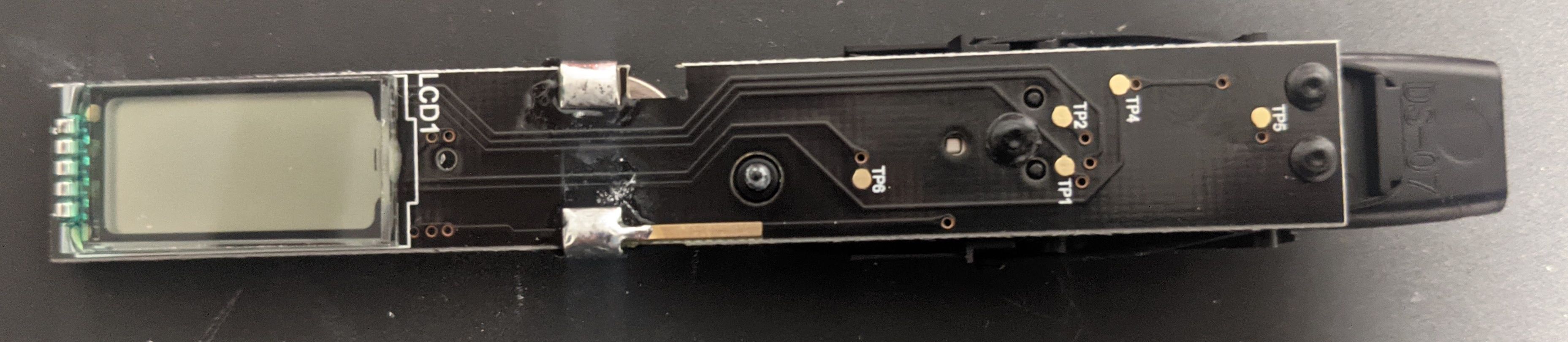
One interesting thing to note is that the test points line up with holes under the sticker on the back. This would allow a test fixture to confirm the device is electrically functional even after assembly.
Here’s the bottom of the cartridge loader:
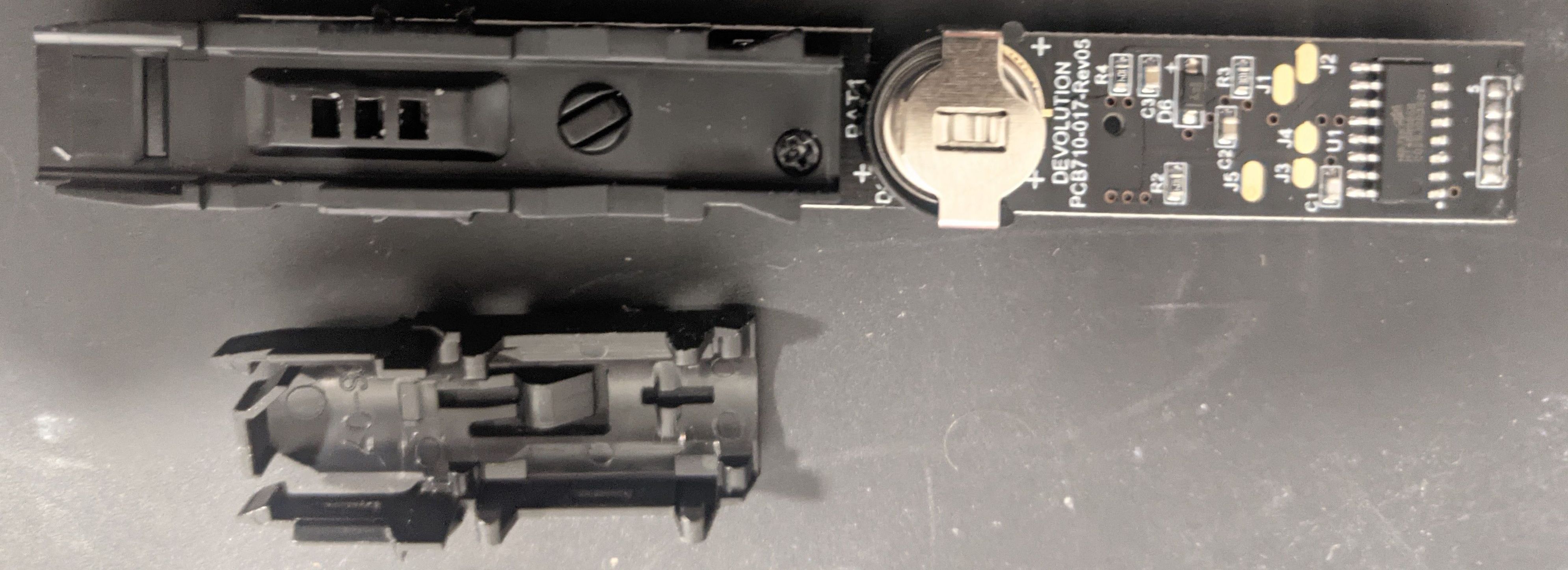
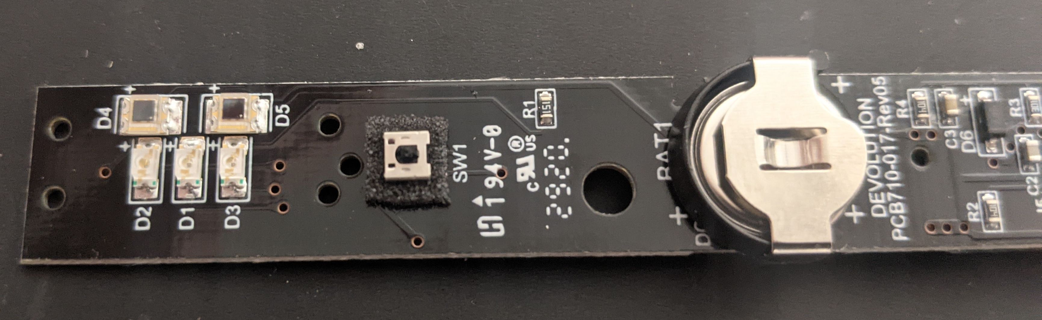
And here are the LED’s and light detectors underneath:
A close up of the microcontroller:
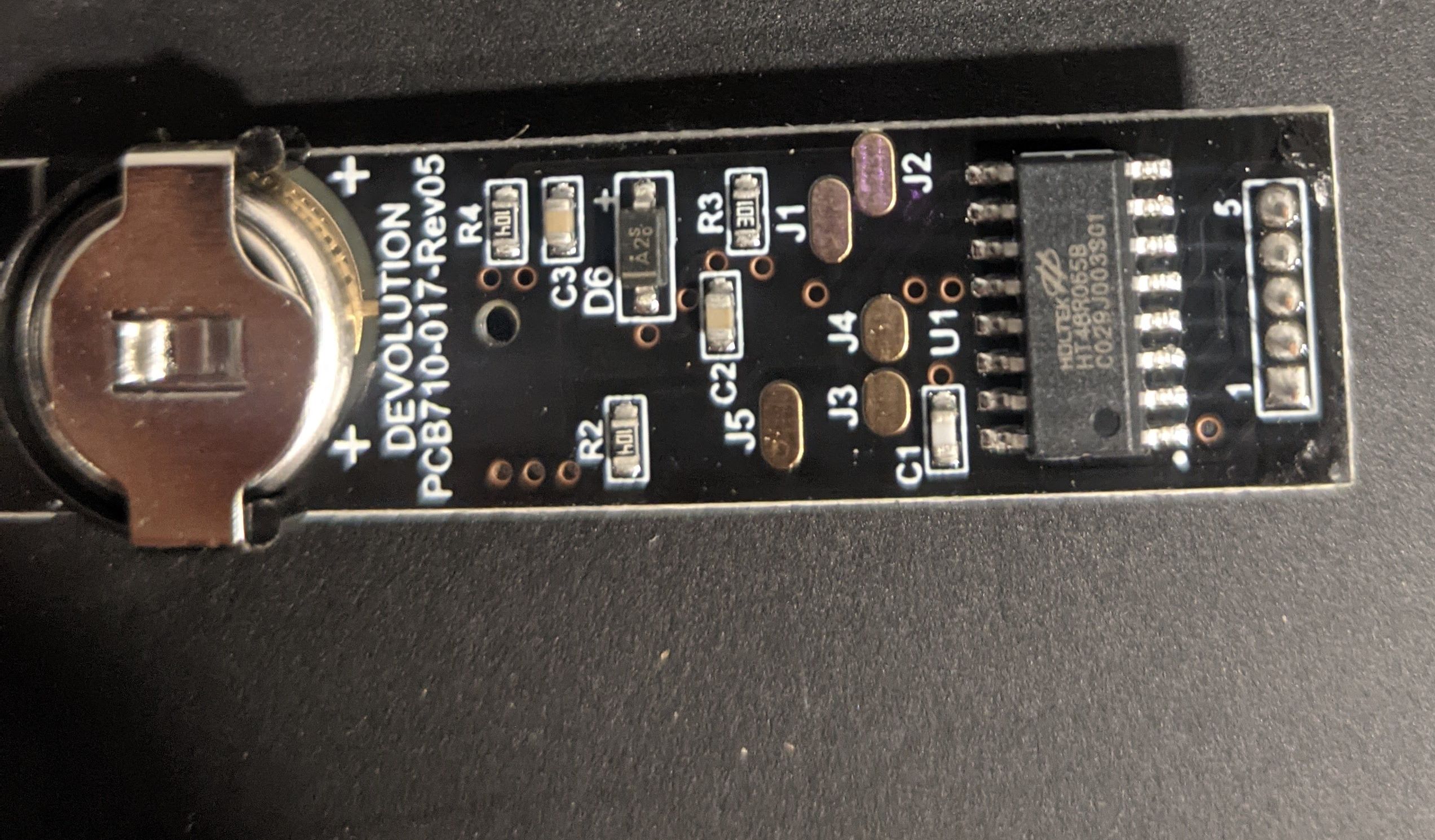
I looked this up, it’s a HOLTEK 8bit HT48R065B. They’re only one time programable, and don’t appear to have a debug interface, so there’s not much I could do with it.
More interesting was the LCD on the back.
It was actually surprisingly hard to find documentation on how an LCD like this is controlled. The vast majority of search results talk about LCD TVs and monitors. When you look at hobbiest devices, you pretty much can only find information on LCD’s with controllers built in where you control pixels or characters instead of the individual segments.
Eventually I found a few useful resources.
First is a project by the EEVblog where he had a custom LCD manufactured for around $100 https://hackaday.com/2018/07/24/custom-lcd-module-is-unexpectedly-cheap-and-easy/
Next I found an app note by Atmel https://www.microchip.com/wwwAppNotes/AppNotes.aspx?appnote=en591293
The diagram at the top of the wikipedia article was also useful https://en.wikipedia.org/wiki/Liquid-crystal_display
What I took away was that the pins you control are attached to electrodes in the shape of the segments. These sandwich a liquid crystal with a common electrode on the other side. Putting a voltage differential between the segment and common electrode causes the crystal to polarize which is visible due to a polarizing film on the LCD.
When I probed the LCD pins with the device on, I saw that the inputs were pulsing at 20KHz. The Atmel app note mentions this is prevent the display from degrading due to electrophoresis.
It was easy enough to wire the display to my own microcontroller and figure out the pins.
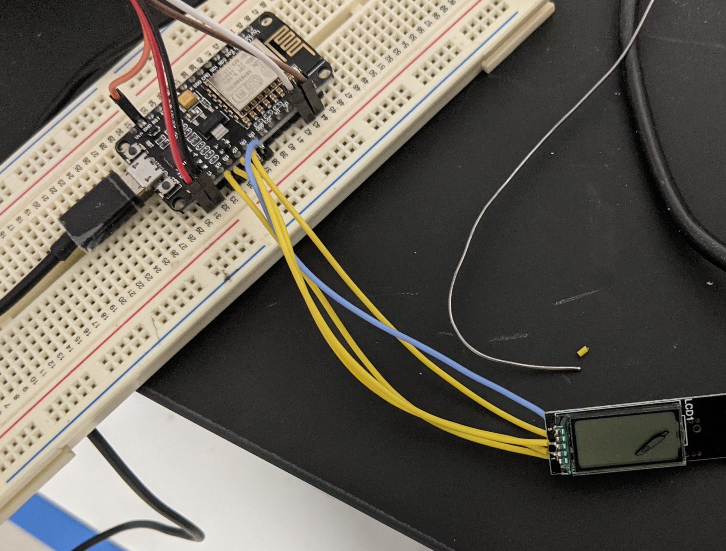
I used this dummy test code to control the display:
1
2
3
4
5
6
7
8
9
10
11
12
13
14
15
16
17
18
19
20
21
22
23
24
25
26
27
28
29
30
31
32
33
34
35
// COMMON
#define PIN_COMMON 14
// SMILE
#define PIN_SMILE 12
// CIRCLE
#define PIN_CIRCLE 13
//BOOK
#define PIN_BOOK 15
//STICK
#define PIN_SICK 3

void setup() {
  pinMode(PIN_COMMON, OUTPUT);
  pinMode(PIN_SMILE, OUTPUT);
  pinMode(PIN_CIRCLE, OUTPUT);
  pinMode(PIN_BOOK, OUTPUT);
  pinMode(PIN_SICK, OUTPUT);
}

// For each period, the segments that are in the
// opposite state as the common pin will be visible
void loop() {
  digitalWrite(PIN_SMILE, LOW);
  digitalWrite(PIN_CIRCLE, LOW);
  digitalWrite(PIN_BOOK, LOW);
  digitalWrite(PIN_SICK, LOW);
  digitalWrite(PIN_COMMON, HIGH);
  delay(25);
  digitalWrite(PIN_SMILE, HIGH);
  digitalWrite(PIN_CIRCLE, HIGH);
  digitalWrite(PIN_BOOK, HIGH);
  digitalWrite(PIN_SICK, HIGH);
  digitalWrite(PIN_COMMON, LOW);
  delay(25);
}
All in all seems like a solidly made little product. I’d guess that the cost of materials is on the order of a couple dollars, though I imagine the custom cartridge loader might dominate the production cost. The design was so simple it reminded me of something you’d see in the Zachatronics game Shenzhen IO.
The one somewhat surprising piece of its operation is that it keeps track of it’s state between uses while not appearing to have any write-able non-volatile memory. It is looking for a spike in estrogen, which it claims to do by comparing with the previous day. This implies that even when it appears to be off (LCD is blank). It is really keeping its RAM set in some sort of low power mode at least for the week you’re supposed to use it for testing.
It’s so simple that it’s not surprising the small watch battery could go for years in a low power state, which is probably a more common way of tracking persistent state then I’d have guessed.