
Extending Saleae Logic To Reverse Engineer LED Remote
I tried out Seleae Logic 2 to reverse engineer the controls for an LED module. I ended up writing an extension speed up decoding the remote control buttons.
The LEDs
I’m planning on making a traffic light costume for my daughter (article TBD). I wanted to make it so that the colors would change based on whether she was moving or not.
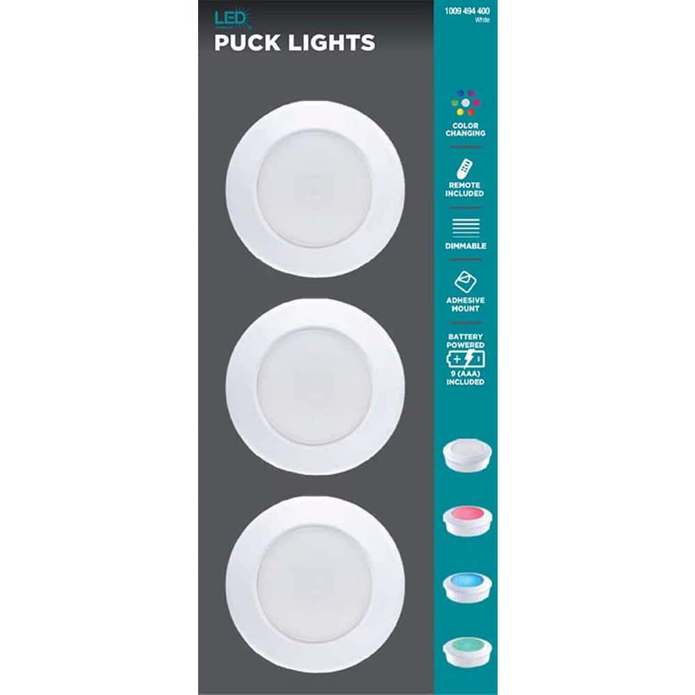
On an unrelated trip, I checked out Home Depot to see what sort of tap lights they had to potentially use, and saw their LED Battery Operated Puck Light with Dimmable RGB Color Changing and Remote Control (3-Pack). Here’s the manual for posterity. I figured this might be an easy way to have the 3 lights I could control the colors for and made an impulse buy.
Here’s what’s inside them:
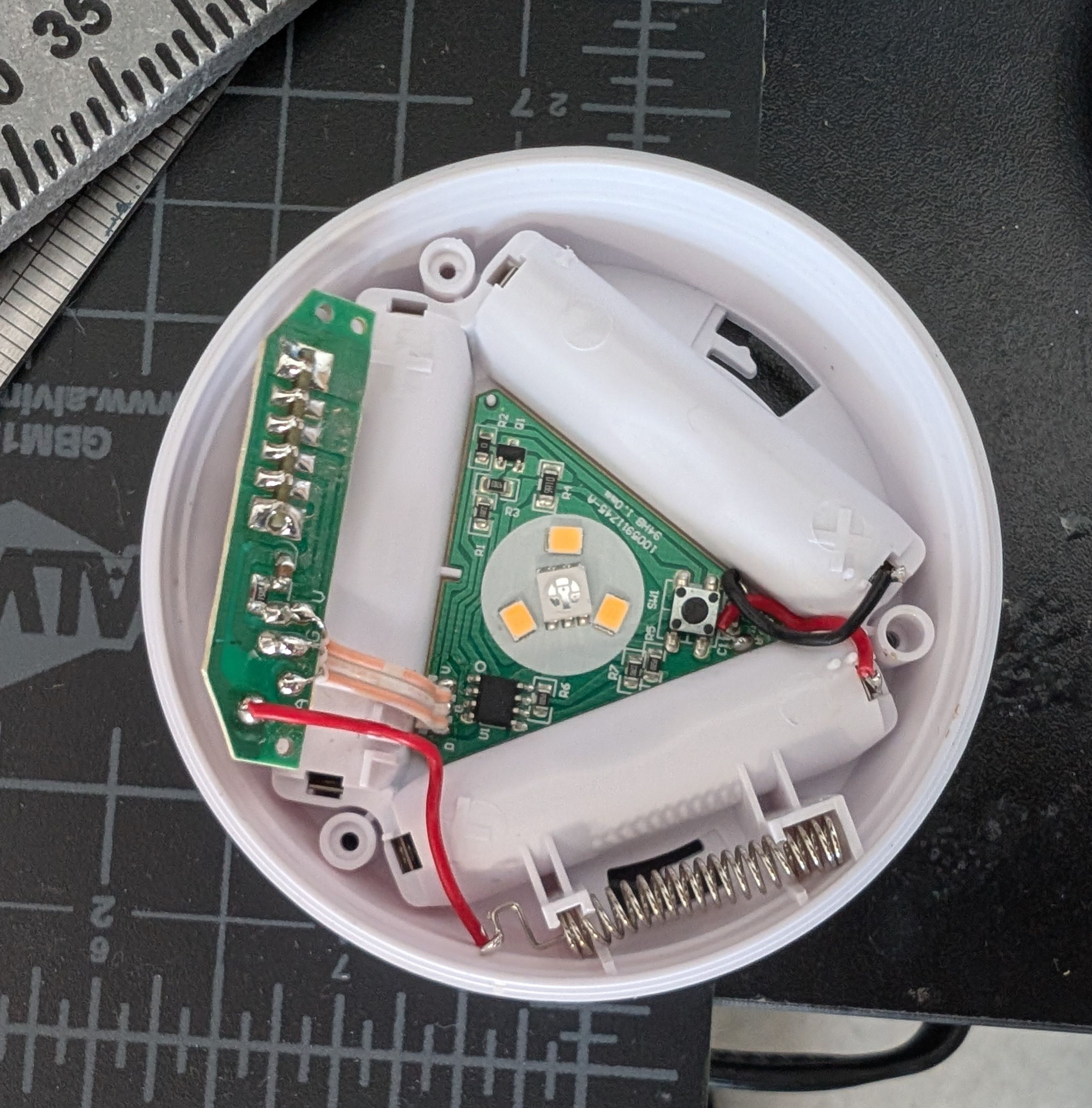
The main board connects to a 433MHz RF receiver board board by a 5V, GND, and data connection.
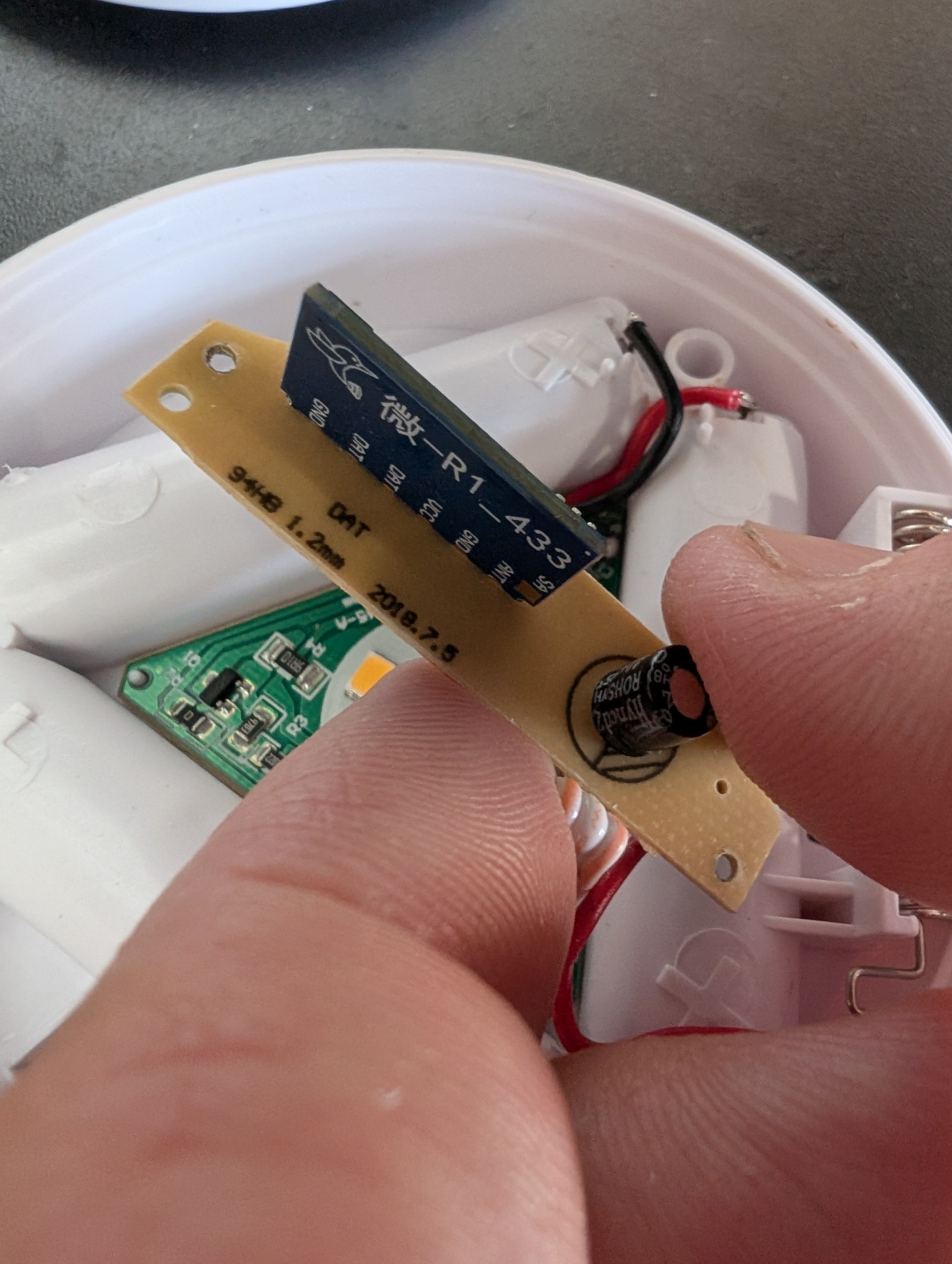
The spring is the antenna connected to the RF board.
Interestingly, the remote control has an IR output, but the board doesn’t have any IR receiver. Presumably the hardware is modular so that it can have the RF receiver swapped with an IR receiver.
In the end I decided that these would probably not be a great fit for building the costume, but by the time I decided that, I was sunk for enough that I decided to finish reverse engineering them.
Control Protocol
I had previously dealt with 433MHz signaling in my weather station reverse engineering. Getting started here was pretty similar.
The first thing I did was probe the board with the scope. The data line from the receiver board was filled with seemingly random 3.3V digital signals. When I pressed a button on the remote I could pick out a repeating sequence among the random noise. The receiver constantly outputs whatever noise it picks up, and only has real signals when the remote is active.
Looking at these signals, they weren’t exactly like anything I’d seen before.
Getting Started With Salaea Logic 2
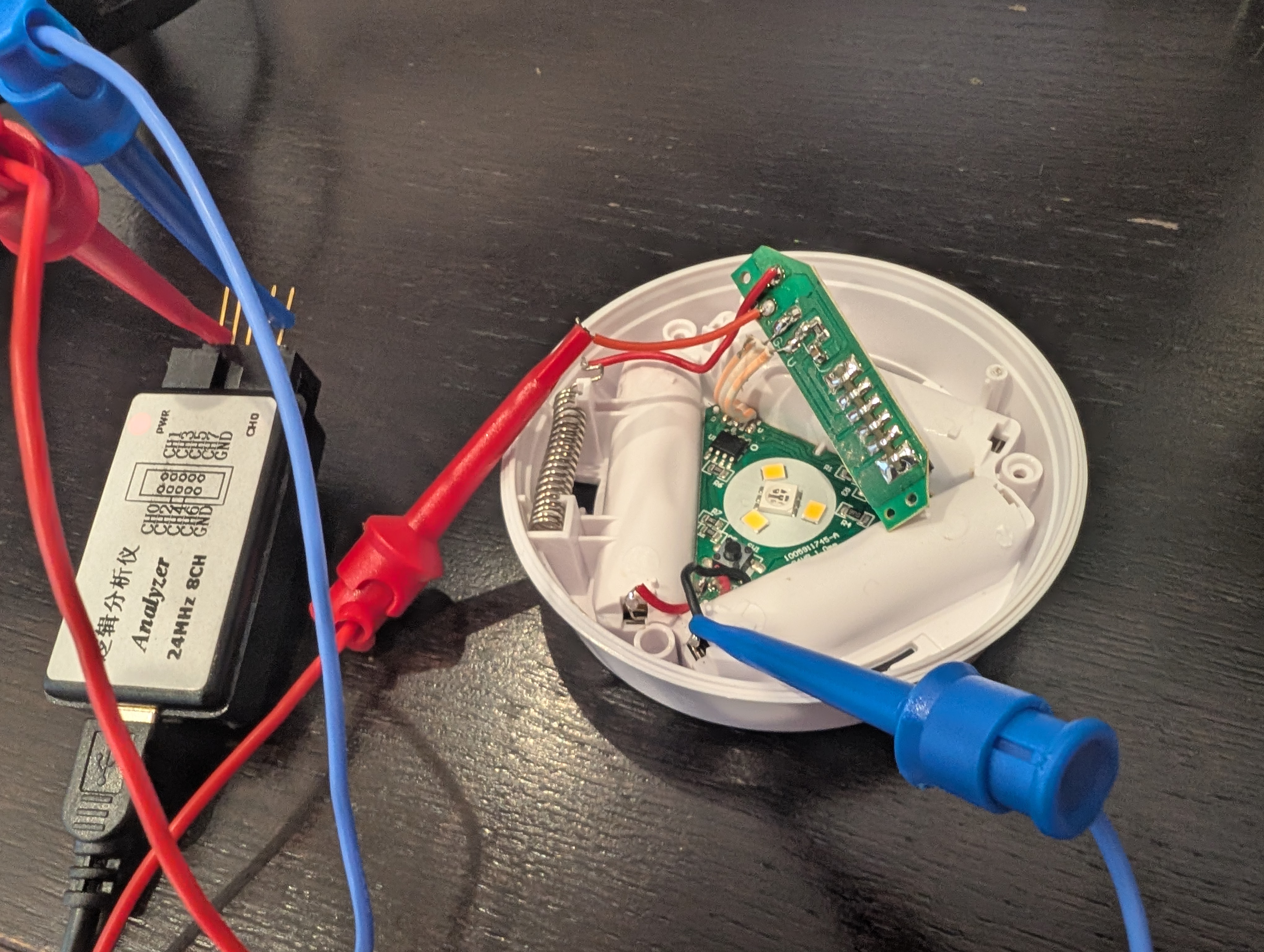
To make analyzing the data a bit easier, I decided I would try out a $10 logic analyzer that’s a clone of a Salaea board.
These boards have no display, and need to be used with the open source PulseView or the Salaea Logic 2.
While the board claimed to support 25MHz sampling, it would timeout if I went above 4MHz. It seems like this was due to the buffer filling since the PC wasn’t pulling data off fast enough. While this might have been something I could have fixed by switching to Linux and messing with thread priorities, I didn’t investigate further since 4MHz was plenty fast enough.
I soldered some wires to break out the signal, and captured some examples.
Determining Signal Structure
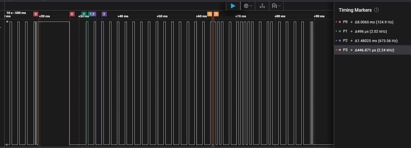
The main characteristics of the signals were that they started with 8ms high, then 3-4ms low. After that there were a sequence of 0.5ms pulses. While at first I thought this might have been Manchester code, the sequences didn’t make sense since the pulse all had the same duration.
After some searching I found out this was likely “Differential Pulse Position Modulation”. See https://www.pcbheaven.com/wikipages/Pulse_Position_Modulation/ for an explanation. The key to finding this was searching for IR remote control signalling schemes.
Initially I spent some time looking at https://github.com/Arduino-IRremote/Arduino-IRremote and https://www.sbprojects.net/knowledge/ir/nec.php which are great resources for understanding IR remote control codes. However, the details of the signal from this remote didn’t appear to match any of the standards:
- It starts with a 8ms high
- It is followed by 3-4ms low
- This is followed by a sequence of 0.5ms pulses with gaps of either 0.45ms or 1.5ms.
- At the end there is a 0.1ms gap followed by a 0.25ms pulse
Creating an Differential PPM Extension for Logic 2
Logic 2 supports a bunch of different digital signal structures, but does not support PPM. Initially I just decoded by eye, but to get the full set of signals I decided to create an extension to help.
Really, to add a new decoder, you’re supposed to create a binary library using their SDK https://support.saleae.com/saleae-api-and-sdk/protocol-analyzer-sdk. However, this seemed pretty complicated to get started with.
On the other hand, writing an extension is extremely simple: https://support.saleae.com/extensions/measurement-extensions/digital-measurement-extensions. It’s just a Python script that gets the data and produces a set of values.
The problem is that extension can only output numeric values that cover a selected range. This is to cover things like computing measurements like counts or averages across a section of data.
To get around this and output a series of bits, I made an optional parameter in the code that could set a file to write the results to so they could be written to a file. I also made the extension report an integer made up of the decoded bits that could be converted to binary.
The code can be found at: https://github.com/axlan/saleae-diff-ppm-decoder
The README there goes into a lot more detail on how this extension works. While it could be used through the GUI, using the file output really streamlines looking at the decoded bits.
Looking at the Decoded Data
The commands all appear to be 33 bits long. It’s a bit unclear if there’s a special start or stop bit. Here’s the contents that seemed to be constant:
1
2
3
4
5
6
7
8
9
1, 1, 1, 1,
1, 1, 1, 1,
1, 1, 1, 1,
1, 1, 1, 1,
0, 0, 0, X,
X, X, X, X,
0, 1, 1, X,
X, X, X, X,
1
Typically IR PPM commands start off with an address followed by command and some sort of error detection contents. For NEC the error detection is repeating the inverted address and command data.
It does seem like the command starts with 0xFFFF as the address followed by an 8 bit command and an 8 bit checksum, however I wasn’t able to determine the algorithm used. This is then followed by a stop bit.
See the example code in the followed section for the complete bit sequences.
Testing Signal Generation
Once I captured the bits used for each of the commands, I came up with a simple test script:
https://gist.github.com/axlan/b4b21129c1653d637404497dea26ffdc
I connected my microcontroller in the place of the RF receiver and confirmed tha the commands worked.
After some testing I determined that the artifacts after the stop bit weren’t necessary. I also found that I needed to repeat the power on command several times for it to take. Presumably this is for some sort of power saving mode.
Conclusion
Like most of my attempts to reverse engineer cheap lights, this was probably a bit of a pointless exercise. However, it was interesting to learn the ins and outs of Logic 2.