
Toy AVR OS
As an educational project I could do purely in software, I decided to make a toy OS for an AVR microcontroller from scratch.
![]() For the impatient, here’s a video of the final demo
For the impatient, here’s a video of the final demo
I wanted a cutesy name so I chose KittyOS and made the logo. Unsurprisingly, I’m not the first to use the name and found https://github.com/carangil/cat644 which is actually a very interesting surprisingly related project where someone wrote a retrocomputer emulator to run on a Atmega644.
This is by far the longest write up I’ve done. I wrote it as I was going through the process, with additions after the fact. To get most of the meat without going into the weeds on the particular struggles I faced, I recommend skipping between the Intro, Setting Up Task Switching, and the last few sections starting with Boot Loading.
Table of Contents:
- Intro
- Development Environment
- Setting Up Task Switching
- Building the Tasks
- Multi-task Serial Communication Version 4
- Boot Loading
- Writing the Final Scheduler Version 5
- Controlling the Scheduler
- Final Thoughts
Intro
Motivation
For most of my recent software projects, a huge part of the process is figuring out the existing libraries to build off of, to get the results I want with minimal coding. Before the rise of the Arduino, it felt like more development was lower level (bit twiddling, setting up interrupts, configuring registers, etc.), and more focused on the specific features of a particular chip. We live in a better world now where these are often unnecessary, and it’s way easier to get started without needing a lot of arcane knowledge on how chips work.
For this project I want to go the opposite direction. I’m going to attempt to make a very very basic OS from as close to scratch as possible.
This comes on the heels of spending a large part of my professional career doing development on embedded systems. I’ve slowly gotten more comfortable with some of the black magic of how processors work and how operating systems are constructed. I don’t have much formal knowledge of how a real OS is made, but I wanted to see if I know enough to make something interesting.
I decided to design my OS for a 8-bit AVR microcontroller since:
- Relatively easy to understand - They don’t have a lot of the features that make ARM or x86 devices complicated.
- Easy to simulate - The IDE Microchip Studio has a really nice simulator built in that pretty much does everything I need for development.
- Easy to test hardware - Chips, programming tools, and development boards are cheap and I had some lying around.
- Simple assembly - The hardware instructions set for these processors is fairly simple with only 130 or so instructions.
- Already fairly familiar with AVR architecture - I first used these chips over 10 years ago.
I’m specifically targeting the Atmega168 processor used in some of the older Arduino boards since I had one handy.
The Atmega168 datasheet is basically the only reference I’m using for this work. I’m a big fan of the AVR data sheets. They’re long and comprehensive, but are generally pretty well organized and clear.
What I’m Not Doing
While I’m going to go into some detail on everything I’m doing, there’s too many low level processor concepts that I’m going to gloss over. Rather then try to explain my code in detail, I’ll mostly be describing my high level design.
I’m also not trying to make a generally useable framework. This is an educational project and I’ll be making tradeoffs that wouldn’t make sense if I was trying to write a real tool.
What do I mean by OS?
I’m not trying to build anything that meets a formal definition of an OS, but I’d like to see how far I can get with the following features.
Task Scheduling
This is the most basic feature I want to implement. Here, I want to be able to write pieces of code that describe “tasks”. Each of these tasks can run in parallel with their own stacks and are mostly self contained.
The MCU I’m targeting only has a single core, so there’s no true concurrent processing. Only one thing can run at a time, and a scheduler will switch between the tasks.
Often in “bare metal” (no operating system) design, you create code with a structure similar to:
1
2
3
4
5
6
7
void main() {
	while (true) {
		DoThing1();
		DoThing2();
		DoThing3();
	}
}
The problem with this is that each function needs to complete before running the next one. This can make things more complicated if there are long running sections which usually involves using state machines.
Using a task scheduler trades off needing to explicitly manage this. Instead, the state for each task is stored in its stack, and there’s a scheduler that handles choosing which task to run and swapping stacks. I’m not going to go into the details of how stacks work in programming but here’s a decent overview http://www.ee.nmt.edu/~erives/308L_05/The_stack.pdf.
While I knew this was the main feature I wanted to implement, there are some extra complications I could choose to add or not.
Task Preemption / Priorities
Normally in MCU development, you want the program flow to be completely predictable. This lets you know exactly how many microseconds any section of code will take to finish. Typically, if you want to support a task scheduler, that means that you need a way to indicate a task is “at a good stopping point”. This usually would be when it needs to wait for for some external data, or just delay a fixed amount of time. At those points the task will “yield” allowing another task to run. When that task yields the scheduler will check if the first task should be resumed.
This could be fine, but if you have a bug or an unexpected behavior, a single task could end up running for too long. This can prevent anything else from running.
One way to address this is to have the scheduler trigger on a timer. There it can choose to stop the current task and switch. Usually, preemption is paired with a concept of priority. Higher priority tasks ready to go will run before lower priority ones.
The cost of preemption is that any given chunk of processing might be interrupted by another task. This can make the processing time less consistent and make synchronization bugs more likely.
System Calls
In most OS environments there’s a differentiation between code runner under the user, and code running under the kernel. Here’s a quick rundown on one way this is implemented in Linux. While this makes more sense in a multi-user environment, the distinction could still be made for a task based system. Specifically, I could use a set of special calls to access the hardware functionality that needs to have its access managed across tasks.
For instance I could make a print function that stores data without blocking to be sent out of the serial port using interrupts. Another example would be adding cross task synchronization like mutexes or message queues.
Multiple Applications
The last big area of features that would be interesting is allowing for the concept of applications that can be loaded and run from a secondary memory like an SD card.
This is a bit challenging since the the MCU can only execute instructions loaded in its flash. That means that basically any concept of multiple applications is closer to just being a bootloader reflashing the chip more then being able to quickly switch between programs.
However, I think there might be some stuff to still do here. First off, just writing a bootloader is interesting. Also, I think it would be interesting to have a concept of relocatable programs that can be stored in flash. One idea would be to create a format somewhat similar to an ELF file. When the bootloader loads this and writes it to flash, it changes some of the memory locations based on the offset it’s being stored to. The bootloader would also have a table tracking the loaded applications which could be switched between.
Some additional features this opens up would be shared libraries, or even adding memory protection by restricting the memory space of the applications.
Development Environment
Microchip Studio
Microchip Studio is a reskinned version of Microsoft Visual Studio specifically tailored for programming some of the microcontrollers sold by Microchip. The basic package is free, thought there’s a pro version with a better compiler and other tooling.
Microchip Studio has a few pieces that I would be using extensively:
- It packages the AVR cross compiling GCC build tools together.
- It automates a lot of the boilerplate you’d need to specify the AVR dependencies and settings as part of the project creation.
- It provides an extensive and extremely useful debugger. Honestly, I’m amazed at how well this works, both with the simulation, and hardware debugging.
- It provides and interface to the AVR compatible programming hardware.
The main downside is that this is a Windows only tool. It also obfuscates some of the details of what’s happening during the build. Fortunately, you can see most of the underlying GCC commands in the logs which was a big help in learning some of the quirks of compiling AVR code.
The Hardware
I’m using an old Arduino Diecimila board with an Atmega168. The Arduino board is basically just supplying the chip with power, a clock, and the USB-to-serial converter.
Atmega168
The vital specs for this chip are:
- 16KB flash program memory
- 1KB general purpose RAM
- CPU running at 16MHz
and here’s the overview of the peripherals:
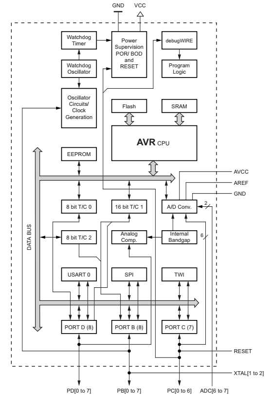
Since this chip is part of an arduino board, it originally had a boot loader, and some of it’s fuse settings were modified from the defaults. I ended up disabling the the BOOTRST, but otherwise left the values at their “normal” Arduino values. I think the only values that are different from the chip defaults are that the clock is configured to use the 16MHz external occilator, and the boot sector size is 1024 words big.
Here’s the values I’ll be using.
1
2
3
EXTENDED = 0xF9
HIGH = 0xDD
LOW = 0xFF
Debugger
I bought a new tool specifically for this project, an ATMEL-ICE debugger. I’ve never actually owned a device that could debug a microcontroller, they tend to be expensive and limited to a subset of devices. Regardless, I decided to invest in an Atmel ICE to have an easier time once I was actually testing on hardware.
The Atmega168 chip I’m working with uses the debugWIRE protocol which is one of the protocols the ICE supports. Getting things connected was extremely easy. Since I’m using an Arduino Diecimila I could just connect it to the ISP pins, and the programming functionality worked fine.
When I tried to actually use the debugger, I was given a warning that the debugWire fuse would be enabled, and that this required the reset signal be free. I hit OK, but the connection failed. Even worse I could no longer connect using the ISP debugging interface. I realized that Arduinos trigger reset when the USB-serial connection is connected, and that this might interfere with the debugWire interface. Sure enough, I found an article that went into this in detail: https://awtfy.com/2010/02/21/modify-an-arduino-for-debugwire/. I was able to de-solder the capacitor and sure enough the debugWire started working.
The one additional complication was how to turn the debugWire off to restore normal programming functionality. Eventually I found this button:
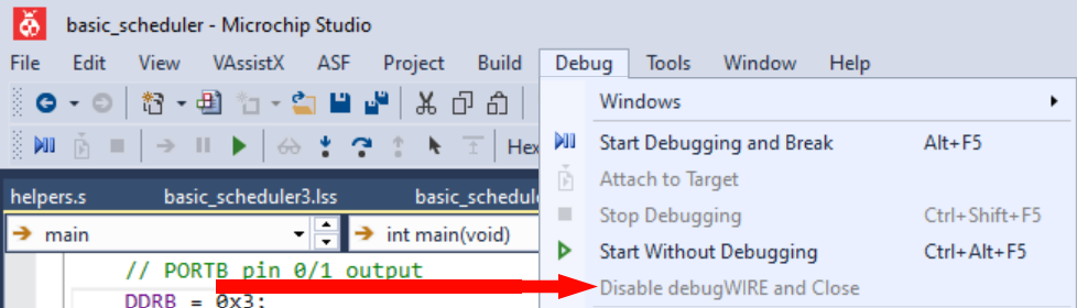
While I was able to get through the basic development without needing the debugger much, once I was loading programs onto the hardware, the debugger became invaluable for getting snapshots of the device state and stepping through the operation.
Coding
Since I wanted to rely heavily on the simulator I did my coded in Microchip Studio. I decided to do a GCC C build as the basis of my project, and include additional assembly as needed. I probably could have done it entirely in assembly, or entirely in C with some inline assembly, but I thought this was the clearest way to organize things.
I’m fairly novice at assembly, and didn’t realize going in that there were actual different variants used in a lot of the AVR examples online. One variant is for the GCC compiler, and the other was for the Atmel AVR compiler. Since I’m using GCC, everything I mention here will be in that form.
I found these a useful starting point: https://ucexperiment.wordpress.com/2012/02/09/mixing-c-and-assembly-in-avr-gcc-and-avr-studio-4/, https://people.ece.cornell.edu/land/courses/ece4760/FinalProjects/s2012/xg46_jy363/xg46_jy363/Reference/Mixing%20C%20and%20assembly%20language%20programs.pdf with https://gcc.gnu.org/wiki/avr-gcc useful for additional reference like what registers the compiler expects to save.
Setting Up Task Switching
To make this project more manageable I tackled it as a series of iterative “releases” that would bring the main features into some usable form piece by piece. This first version just handles a basic form of task switching.
I described task switching a bit in the intro, but the core idea is that I need a way to take the current state of the “task”, save it, then load the previously saved state of another task.
While its purpose isn’t multi-tasking there’s a solution to this problem has been a core piece of processor design for so long that even this basic 8-bit processor has hardware to support it. That solution is “the stack”.
The use of a stack in programming is an entire subject of it’s own http://www.ee.nmt.edu/~erives/308L_05/The_stack.pdf. For the Atmel168, the concept of a stack exists in 3 different layers of abstraction.
- A stack is a data structure that you can choose to use in the code you write.
- The GCC compiler uses the concept of a stack as a key part of how it compiles subroutines. It has a bunch of conventions that govern this behavior.
- The Atmel168 processor has a few features that explicitly support the subroutine use of a stack. It has a few instructions that let subroutines be used with a stack more efficiently, and it has a dedicated “stack pointer” register.
To manipulate the stack for handling multiple tasks, we’re going to need to go between all three of these layers.
Version 1
Here is the code for my first pass at a tasks switching. The task functions just toggle output pins. See the fairly thorough documented code here: https://github.com/axlan/avr_scheduler_experiments/tree/master/basic_scheduler
The program starts out using the normal stack growing from the end of the memory range. It then uses assembly functions to replace the stack pointer with an address to a reserved memory range for the task. This memory is initialized with the address of the task in flash.
This is mostly an exercise in copying the start function pointers to the tasks’ stacks and doing the assembly to store and restore the stack pointers. The tasks “yield” to have the execution return to the original scheduler’s execution. This is repeated for each task being run.
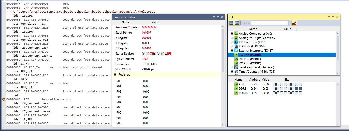
This code was just designed and tested in simulation, I was able to use the IO view in the IDE to watch the pins virtually toggle and confirm my design:
Version 2
To make this scheduler even somewhat useful, I added the use of the hardware timer1 so that the tasks can go to sleep for an amount of time instead of just yielding:
https://github.com/axlan/avr_scheduler_experiments/tree/master/basic_scheduler2
This example starts to show how much overhead my admittedly not optimized scheduler takes.
- The check to see if a task is still sleeping: 40 cycles
- Switching to the task: 27 cycles
- Updating the next wake time: 19 cycles
- Switching back to the scheduler and incrementing the task: 59
Counting the overhead from a whole loop, it’s about 148 cycles of overhead (148us at 1MHz, 9.25us at 16MHz). This isn’t a ton, but it’s also not totally trivial.
I decided to actually test this on a real Arduino board. Attaching the scope to the output pins shows everything working as expected:
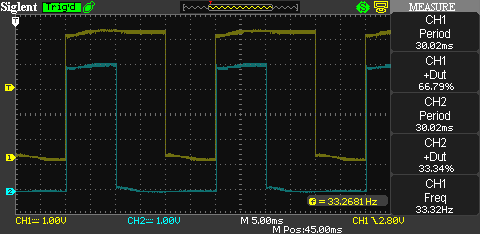
(task1 makes CH1 go high for 20ms and low for 10ms, while task2 makes CH2 go high for 10ms and low for 20ms)
Building the Tasks
I wanted to move a bit more toward being able to specify independently compiled “applications”. The idea is that I could set up a new project, compile it separate from my OS, then be able to load and execute it on a running device.
The limitation I was giving myself here, is that I’m not going to use GCC or the linker to compile together the pieces like you would with a library, or even just different modules in the same build. I’m basically trying to reinvent the concept of executables.
There’s a lot of ways I could approach this, so first I decided to focus on understanding how I would be building up “relocatable” code segments. For this version I separated the code across two separate projects:
https://github.com/axlan/avr_scheduler_experiments/tree/master/basic_scheduler3 https://github.com/axlan/avr_scheduler_experiments/tree/master/task3
The idea is that if I could get this to work, I could use a table to track the tasks that are in flash, and modify them during runtime.
Version 3 Task
The task3 project is the same code as one of the tasks from the previous version, except now it needs to compile on it’s own.
To do this I needed to figure out:
- How to make sure the generated code would still be able to run properly when running at a different memory offset.
- How to call code in the scheduler project.
- How to dump just the code for the task without any of the setup or teardown sections.
- What other limitations do I need to impose (like only declaring values on the stack) ?
One concern I had is that the code would compile with references to its absolute position in memory. There are only four instructions in this processors instruction set where this might be an issue:
- IJPM - This loads an absolute memory address from the Z register and jumps there.
- JMP - This instruction contains a 22 bit absolute memory address to jump to.
- ICALL - This loads an absolute memory address from the Z register and jumps there updating the stack.
- CALL - This instruction contains a 22 bit absolute memory address to jump to and update the stack.
The compiled version 2 example didn’t use any of these instructions, so I might be able to get away with ignoring this issue for awhile. I imagine there’s probably ways to force GCC not to use them. The one limitation is that the RJMP and RCALL versions of this instruction which are used can only jump 8KB max. This should be OK though since I’m going to limit the size of an application to less then 8KB for this processor anyway.
For calling the delay function, the easiest way to call functions from the scheduler project is just to hard code the address. I could compile the other project and record the address it happens to be, but I’ll be using the linker to force it to a particular location. My first thought was to use a type cast like: (void (*delay_sig)(uint16_t))0x1000 where 0x1000 is the program counter address (this is half the byte address where the instructions are mapped to). Delaying 10 clock ticks would then be: ((void (*delay_sig)(uint16_t))0x1000)(10);.
I was curious so I looked at the generated assembly. I was a little surprised that that this instruction generates an ICALL instruction. In this case this is fine since I am jumping to an absolute location, but I was surprise that ICALL was used instead of CALL. It requires two load instructions so it take 5 cycles and the extra register churn instead of 4. Not sure why GCC doesn’t use this, but I guess CALL isn’t universally available across the chip family.
Since I wanted this project to build fully linked, I built it as an executable. This means it generates an ELF file that describes all the memory allocations and metadata in a table, and a hex file which is just the raw data that gets sent during programming. Looking at the .lss file, the compilation results in the first 128 bytes of program memory being used for initialization and interrupt tables, and the last 4 bytes being used as a kind of safety stop. Looking at how Microchip Studio handles the compilation artifacts, I realized that the compiler comes with objcopy.
1
2
3
4
5
6
Finished building target: task3.elf
avr-objcopy.exe -O ihex -R .eeprom -R .fuse -R .lock -R .signature -R .user_signatures  "task3.elf" "task3.hex"
avr-objcopy.exe -j .eeprom  --set-section-flags=.eeprom=alloc,load --change-section-lma .eeprom=0  --no-change-warnings -O ihex "task3.elf" "task3.eep" || exit 0
avr-objdump.exe -h -S "task3.elf" > "task3.lss"
avr-objcopy.exe -O srec -R .eeprom -R .fuse -R .lock -R .signature -R .user_signatures "task3.elf" "task3.srec"
avr-size.exe "task3.elf"
For me these were in C:/Program Files (x86)/Atmel/Studio/7.0/toolchain/avr8/avr8-gnu-toolchain/bin/ which can be referenced in the IDE with the macro: $(ToolchainDir)
This command line tool is basically built for copying and converting sections of elf files. After a bit of messing around I could dumpy the raw binary of my task (avr-objcopy -O binary --only-section=.text.* task3.elf output.bin). The .text.* picks of the memory segment .text.main that points to the code I write starting in the main function.
Since my basic implementation works for this test application, I didn’t spend time figuring out how to generate build errors if I do something that generates instructions that reference absolute memory locations.
Version 3 Scheduler
Once again the functionality here is basically the same as Version 2. The only differences are that I needed to call the code I generated from the other build, and I needed to force the delay function to be at a particular address.
One option would be to edit the final binary, which would have been fairly straightforward, but I wanted to end up with a single ELF file containing the scheduler and the task. This would let me run it in the simulator. The way that’s most in line with the usual compilation process is by using a custom linker script.
It may be my lack of experience with them, but I’ve always found linker scripts to be a fairly poorly documented, with poor integration in most build tools. This was no exception, and I spent a lot of time on trial and error trying to get something that’s “fairly simple” to work.
Since Microchip Studio is built on Visual Studio, it tries to abstract the linker script somewhat in the project menu. Under Project Properties -> Toolchain -> AVR/GNU Linker -> Memory Settings you can specify memory regions in the project itself. There’s also a blurb there about how GCC had to do a bit of a hack when specifying the memory regions.
You can add a verbose flag (-Wl,--verbose) to the miscellaneous settings to see what it’s currently using in the build output:
That’s certainly fairly complicated. Looking at it, here are a few of the things it’s doing:
- There are a few distinct “memories” on the AVR that will need to be programmed separately. This file sets up a way to reference them in the program as one continuous memory range, even though they will be treated separately by the programming device in the end.
- FLASH
- SRAM
- EEPROM
- fuse - These are a special set of bits that configure the device before startup. They set some of the modes and features that are enabled and things like clock source.
- lock - These are a special set of bits that restrict read/write access to the device.
- There’s also some signature sections, but I think these are read only, or not enabled on this device.
- There are 16-bit and 32-bit instructions. Some make a destination on which program regions they can reference (far versus near) make a special destination between addresses that are in the lower 64K words. I think since this device only has 16KB of flash, this is not relevant.
- There’s a ton of
initandfinsections that mark setup and teardown for the executable. I think these are mostly leftover from GCC thinking we might be on a more complicated system. These might initialize some memory regions, but thefinstuff is totally irrelevant. Mostly I can ignore these. - The vector section and “trampolines” I believe refer to the region that will handle hardware interrupts. This is fairly important later if I want interrupts to allow task preemption, but I’ll be ignoring it for now.
- There’s a bunch of stuff for debugging symbols which I don’t need to worry about for now.
- I’m kind of surprised I don’t see mention that certain regions can be reserved for boot loading, but I guess since that’s configurable, it’s not included in the default script.
Now all I needed to do was figure out how to actually reference memory regions that I specified. Here are some of the articles I read on this:
- https://microchipsupport.force.com/s/article/Atmel-Studio--New-memory-section-creation-in-ARM-GCC-linker-script
- http://ww1.microchip.com/downloads/en/Appnotes/doc32158.pdf
- https://microchipsupport.force.com/s/article/Locate-linker-script-for-AVR-devices-in-Atmel-Studio
- https://community.silabs.com/s/article/using-a-linker-script-in-gcc-to-locate-functions-at-specific-memory-regions?language=en_US
The first task was getting the delay function at the desired address. One of the guides gives a method for this, but I took a slightly different route. Here’s what I put at the end of the .text section in the linker script:
__scheduler_end__ = .;
/* "dynamic syscall" functions at 8K. Should add assert to check size of previous sections. */
. = 0x2000;
*(.delay_func)
  _etext = . ;
Initially, I had some confusion over linker script sections versus segments. This stack overflow explains it a bit:
In the above change, I’m adding the section .delay_func to the segment .text. I reference the section in my C code to set the location of the function:
1
2
3
4
5
#define LOCATE_DELAY_FUNC  __attribute__((__section__(".delay_func")))
void LOCATE_DELAY_FUNC delay(uint16_t ticks) {
	current_task->next_run = get_time() + ticks;
	suspend_task();
}
Next, I had to figure out how to combine the program code generated into the task into this compilation. It probably would have been much easier to just encode the data in the C code to be stored in flash, but I wanted something a bit less hard coded. Some Googling turned up that objcopy has a flag for this as well.
avr-objcopy --update-section .tasksection=output.bin basic_scheduler3.elf
This overwrites the linker section .tasksection with the contents of output.bin.
It took a ton of trial and error to get this working, but eventually I came up with the following addition to the linker script:
TASK_MEMORY (rx) : ORIGIN = 0x2400, LENGTH = 7k

...

.tasksection :
{
  *(.tasksection_start)
  KEEP (*(.tasksection_start))
  FILL(0xDEADBEEF);
  . = 0x1C00 - 1;
  BYTE(0xEF)
  ___ROM_AT = .;
} > TASK_MEMORY
This creates a new section for this data in the last 7KB of flash. I then fill that section with a filler pattern, though I mostly did this for debugging, and it’s probably not necessary. It seemed that this section was often being dropped since it didn’t have anything in it during the projects compilation, but it seems like some combination of adding sections and filler got it to be kept.
I was able to automatically run this command so the binary built in the Microchip Studio compilation would have the task in place. I needed to modify the Build Events in the project settings to add these commands.
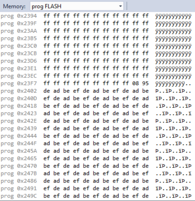
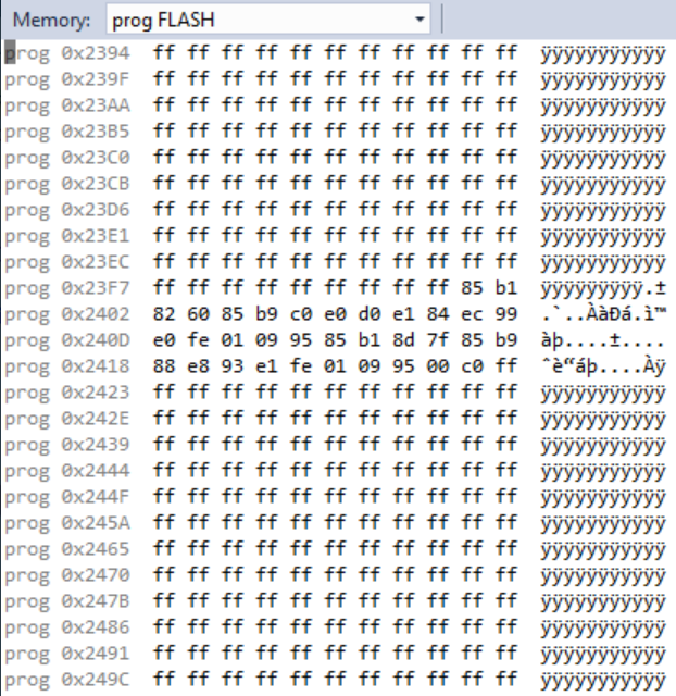
With all this in place I could finally get the tasks to run correctly while being built separately.
Here’s the debugger showing the memory before and after loading the task.
Multi-task Serial Communication
To be able to write even a reasonably simple application, the next step was adding serial communication. I wrote a basic driver to implement a serial Rx and Tx buffer so the tasks could communicate with a host.
https://github.com/axlan/avr_scheduler_experiments/tree/master/basic_scheduler4
I also added a very basic lock mechanism to allow inter-task synchronization.
This was the most coding intensive version since I wrote some non-trivial circular buffering implementation, but this is more in my normal embedded programming wheelhouse. Most of my time here was understanding exactly how the UART TX data ready interrupt I was using behaved.
The read/write calls are:
1
2
3
4
5
6
7
8
9
10
11
12
/**
 * Send as much of the data as possible without blocking.
 * Returns the number of bytes sent.
 */
uint8_t USART_Send(const uint8_t* data, uint8_t len);

/**
 * Read as much of the data (up to len bytes) without blocking.
 * Each task_idx allows for separate tracking of which bytes have been read.
 * Returns the number of bytes read.
 */
uint8_t USART_Read(uint8_t task_idx, uint8_t* data, uint8_t len);
The incoming data is copied to a circular buffer and each task has its own “tail” used to track where it is in the buffer. This avoids needing separate buffers for each task. Using interrupts to provide a non-blocking API added a lot of complexity, but really adds the first aspect of “parallelism” to the code base since tasks can each be waiting on common or different data from the host. One thing I don’t do is define a protocol that could be used in a real system. A real system would need a way to indicate which tasks the data was intended for. Instead in this and other versions I just take for granted that the data can be seen by all the tasks without issue, or I clear the data after the scheduler gets a command message.
Since my tasks were getting more complicated I hit a few issues with my task switching logic. First I realized I needed preserve more registers. I probably went a little overboard by saving everything that the GCC documentation mentioned, but I’m not writing this to be optimal. I also introduced a bug that I don’t fix until much later. Since, I’m using interrupts, I need to protect the updates to the stack pointer. The other thing I noticed was that when I referenced a string it was doing some non-trivial memory manipulation that wouldn’t work for my “relocatable” code approach. Let’s say you have some code like:
1
2
const char* name = "JOE";
print(name);
For an x86 or ARM machine usually the string “JOE” with the null terminating character would be loaded with the rest of the machine instructions that make up the program. When the program uses the variable it’s just referenced from that memory directory.
It’s different for this microcontroller. The executable instructions are being loaded from FLASH. Data in flash can’t be used directly, so when the program first starts, all the constants are actually coppiced to the RAM. This RAM address is where name in the above example would point. You can tell the compiler you don’t want to preload a variable, but this makes it require extra steps to use: https://www.nongnu.org/avr-libc/user-manual/pgmspace.html
With the coding and debugging these issues out of the way, this version produces the following output over the UART:
1
2
3
4
5
6
7
8
Task1 locking
Task1 locked
Task2 locking
Task1 got: !
Task2 locked
Task1 locking
Task1 locked
Task2 locking
Obviously, there’s a ton more features I could add, but this was a good base-line for this exercise.
One additional thing I noticed was that my application was taking up more space then I was expecting:
Program Memory Usage : 2492 bytes 15.2 % Full
I had a hunch it was because I was using floating point to calculate some of the constant values used to set the delay and baud rates. Sure enough, if I just precomputed these it nearly halved the flash usage:
Program Memory Usage : 1392 bytes 8.5 % Full
The reason for this is that there’s no hardware support for floating point, so the algorithms for these calculations need to be kept in memory.
Boot Loading
I had thought I was ready to move on to actually putting the OS demo together, but self programming was complicated enough I decided I needed to do some dedicated experimentation. This was partly because I found the data sheet wasn’t some of the details. The functionality does span many aspects of the chip, and I guess they try to be somewhat generic which can be confusing.
My test code was: https://github.com/axlan/avr_scheduler_experiments/tree/master/boot_test
This app note does a decent job of explaining things.
First off there’s several layers of restrictions on how the flash memory the program is running off of can be modified. These act as fail safes against incorrect/malicious code from corrupting the application binary.
- Part of the flash is designated the boot loader section. There’s a fuse bit that sets this section’s size. Self programming instructions can only be executed from this section.
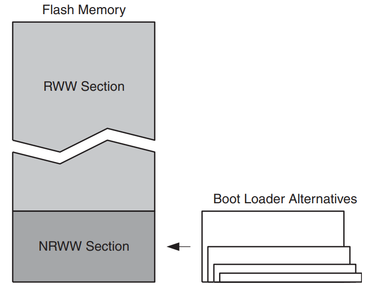
- Part of the flash is designated as read while write (RWW), and the rest is no read while write (NRWW). This determines if the processor will halt while the section is updated and affects how the memory is locked after a write.
- There are lock bits that can limit the chips reprogrammability. This can prevent self programmed modifications, or even disable programming entirely.
- There’s a instruction level handshake involved with actually triggering the store program memory (SPM) instruction.
I hadn’t seen anything like the RWW vs NRWW division that this chip uses before. Modifying the NRWW section is straightforward. Each modification locks the processor so nothing else can be done in parallel. The RWW section is a bit more complicated. Once any part of the RWW flash starts being modified, reading from that or any other RWW section will just return 0xFF. You can keep running code in the NRWW section while these modifications are being done.
For the specific Atmega168 I’m targeting here’s how I understand the layout.
- A “word” is 2 bytes (the minimum size of an instruction). This is often confusing since half the time things refer to the byte offset, and half the time it’s the work offset.
- A “page” is 128 bytes.
- The boot loader section ends at the end of the flash (0x1FFF words) and can be between 128 and 1024 words. With the max boot size reserved that means that the layout is (addresses given in words): app section [0x0000 - 0x1BFF] boot section [0x1C00 - 0x1FFF]
- The layout of the read while write and no read while write sections is static. This lets you put parts of the application code in RWW depending on how you size the boot section: RWW [0x0000 - 0x1BFF] NRWW [0x1C00 - 0x1FFF]
Based on what I’m trying to do, I’d probably want at least the entire UART handling, and memory writing code in the boot loader section. This poses a of a challenge though. Setting up interrupts in the NRWW memory is tricky since you need to enable an alternate interrupt vector table location and actually write it into memory. This would probably mean needing to rewrite a chunk of the linker script and manually specify the vector table. It seems like generally this is done by writing the boot loader code as it’s own application. Rather then do all that, it seems much easier to just ensure that this toy example can just disable the interrupts and poll the UART for data.
I made a test project to try to get a better feel for the SPM instruction used for self programming. The main challenge was figuring out how to avoid using unnecessary time or memory while doing the flash writes.
The pages are 128 bytes so the UART transfer takes 11ms. The flash erase and flash write each are supposed to take about 4-10ms or so.
I wasn’t sure exactly how SPM writes worked so I came up with 3 designs.
- The simple approach of erasing the memory, then receiving the data over the UART and writing it to straight to the flash buffer, then triggering the write. This works as expected but means the UART writes can’t be done in parallel, almost doubling the program time.
- I could receive the data over the UART while the flash is being written and erased and store these in SRAM. This also works fine, but requires setting aside 128 bytes. Since I’m not running other stuff in parallel this wasn’t too big a deal.
- I originally thought that I could receive data over UART while the write or erase was going and write them to the flash buffer. This did not work since it seems like the flash buffer is “busy” during both these operations.
I struggled for awhile with where I needed give flash byte addresses, and where I needed a “word” address.
Writing the Final Scheduler Version
As I put all the pieces together and actually started testing the full system, I ended up having to make quite a few changes from my previous version.
The final code is at: https://github.com/axlan/avr_scheduler_experiments/tree/master/basic_scheduler5
Along with an LED toggle task: https://github.com/axlan/avr_scheduler_experiments/tree/master/task5_2
and an echo task: https://github.com/axlan/avr_scheduler_experiments/tree/master/task5
This code changed a lot:
- It adds the logic for handling the list, enable, delete, and write commands from the host.
- It adds the bootloader functionality for the write command.
- It stores the state for the current tasks in the EEPROM so they are preserved through power cycles.
- I tweaked the serial interface to allow checking the amount of buffered data for reads and writes.
- I changed how the system calls are specified and used by the tasks.
- I simplified how the task relocation works so I didn’t need a custom linker script.
- I fixed a major bug in the task switching assembly.
While a lot of this was just adding the features I wanted to support the demo I want to go into some detail on the system call changes and the task switching bug.
Finding a Better Way to Compile the Tasks
As I mentioned in the previous version, I had noticed strings had issues with my relocatable code approach.
I read through a few more references, along with a lot of stack overflow:
- https://www.internalpointers.com/post/journey-across-static-dynamic-libraries
- http://nickdesaulniers.github.io/blog/2016/08/13/object-files-and-symbols/
- https://docs.oracle.com/cd/E19683-01/817-3677/chapter6-46512/index.html
- https://stackoverflow.com/questions/53985290/how-to-prevent-linker-from-discarding-a-function
After a bit of testing and background reading, I was starting to better understand how the linker works, and what it would take to actually map the code for a task to be able to be loaded at an arbitrary offset.
I wrote this example program as a test.
1
2
3
4
5
6
7
8
9
10
11
12
13
14
15
#include <avr/io.h>

#define SHARED_LOCK ((uint8_t *)0x1150)
extern uint8_t task_idx;
void write_data(const uint8_t* data, uint8_t len);
uint8_t value;

// Dummy tasks to run.
void task1() {
	*SHARED_LOCK = task_idx;
	*SHARED_LOCK= 0xff;
	write_data(&value, 1);
	write_data((const uint8_t*)"123456", 6);
	value = task_idx;
}
After compiling I ran:
avr-readelf.exe -a task5/Debug/library.o
with this abridged output.
1
2
3
4
5
6
7
8
9
10
11
12
13
14
15
16
17
18
19
Relocation section '.rela.text.task1' at offset 0x6d8 contains 8 entries:
 Offset     Info    Type            Sym.Value  Sym. Name + Addend
00000008  00001506 R_AVR_LO8_LDI     00000001   value + 0
0000000a  00001507 R_AVR_HI8_LDI     00000001   value + 0
0000000c  00001612 R_AVR_CALL        00000000   write_data + 0
00000012  00000a06 R_AVR_LO8_LDI     00000000   .rodata.str1.1 + 0
00000014  00000a07 R_AVR_HI8_LDI     00000000   .rodata.str1.1 + 0
00000016  00001612 R_AVR_CALL        00000000   write_data + 0
0000001c  00001704 R_AVR_16          00000000   task_idx + 0
00000020  00001504 R_AVR_16          00000001   value + 0

Symbol table '.symtab' contains 26 entries:
   Num:    Value  Size Type    Bind   Vis      Ndx Name
    20: 00000000    36 FUNC    GLOBAL DEFAULT    5 task1
    21: 00000001     1 OBJECT  GLOBAL DEFAULT  COM value
    22: 00000000     0 NOTYPE  GLOBAL DEFAULT  UND write_data
    23: 00000000     0 NOTYPE  GLOBAL DEFAULT  UND task_idx
    24: 00000000     0 NOTYPE  GLOBAL DEFAULT  UND __do_copy_data
    25: 00000000     0 NOTYPE  GLOBAL DEFAULT  UND __do_clear_bss
The first thing to notice is that this gives each place in the binary where something will need to be relocated and exactly how it’s represented.
Also the Ndx column in .symtab is interesting. It refers to which section each of these symbols are in. 5 refers to .rela.text.task1 which makes sense since the function is in the text section.
COM is SHN_COMMON: “Symbols defined relative to this section are common symbols, such as FORTRAN COMMON or unallocated C external variables. These symbols are sometimes referred to as tentative.”
UND is SHN_UNDEF: “An undefined, missing, irrelevant, or otherwise meaningless section reference. For example, a symbol defined relative to section number SHN_UNDEF is an undefined symbol.”
One thing I was still surprised by was that the .data and .bss sections are still empty. I had expected that since value is allocated in the global space. I guess these aren’t actually generated until the “tentative” value symbol is able to be linked?
Next, we get even more context with:
avr-objdump.exe -h -S task5/Debug/library.o:
1
2
3
4
5
6
7
8
9
10
11
12
13
14
15
16
17
18
19
20
Disassembly of section .text.task1:
void task1() {
        *SHARED_LOCK = task_idx;
        *SHARED_LOCK= 0xff;
   0:   8f ef           ldi     r24, 0xFF       ; 255
   2:   80 93 50 11     sts     0x1150, r24     ; 0x801150 <__SREG__+0x801111>
   6:   61 e0           ldi     r22, 0x01       ; 1
   8:   80 e0           ldi     r24, 0x00       ; 0
   a:   90 e0           ldi     r25, 0x00       ; 0
   c:   0e 94 00 00     call    0       ; 0x0 <task1>
        write_data(&value, 1);
  10:   66 e0           ldi     r22, 0x06       ; 6
  12:   80 e0           ldi     r24, 0x00       ; 0
  14:   90 e0           ldi     r25, 0x00       ; 0
  16:   0e 94 00 00     call    0       ; 0x0 <task1>
        write_data((const uint8_t*)"123456", 6);
  1a:   80 91 00 00     lds     r24, 0x0000     ; 0x800000 <__SREG__+0x7fffc1>
  1e:   80 93 00 00     sts     0x0000, r24     ; 0x800000 <__SREG__+0x7fffc1>
        value = task_idx;
  22:   08 95           ret
Now we can see exactly how the relocations show in readelf are being used. In the actual binary and asm instructions we see these values are currently set to 0. Presumably the linker knows how to go in and fill this with there correct values once this section is actually linked.
Further, I found that by adding the -nostartfiles I could get rid of the startup logic and getting rid of the flags -ffunction-sections -fdata-sections and --gc-sections would keep my sections from being optimized out.
With all this exploration, I now knew how I could compile a task so all the program functionality I wanted was in the .text section. This meant I could reassess how I wanted to actually generate the binary for my application.
Probably the most sophisticated way would be to compile the task as a static library. I could then take the binary and the relocation symbol table and use that as the data I send to the OS. The OS could allocate the stack, .data, and .bss section in RAM and basically perform the same job as the linker and update teh machine instructions from the relocation table based on where it’s going to run the task from in memory.
A step down would be to have the OS send the offset where the task will be stored, and have the host recompile the project based on that. This would use the flags I mentioned to get rid of the startup code, and I could use a linker script to define where the OS shared functions and variables were in memory, and where the task code is in memory. In addition I could map the .data and .bss to somewhere reserved for the task like I’ve been doing with the stack.
The simplest option is just to build the task as a static library and compile it with the scheduler. The only special action is that I’ll need to set the section in the scheduler to make sure it’s at the right offset. I can keep limiting myself to not using global memory to avoid needing to do anything about the .data and .bss sections.
I decided to go to something slightly in between the two simpler options. I’d compile the tasks as unlinked object files, and be able to locate the code at the desired offset by just running the linker.
So the process for writing the OS and tasks ended up being:
- Create a scheduler project with the “kernel” code.
- Create a header file that gives the tasks all the information they need.
- Create projects for the tasks that use the header.
- Add new boot loading functionality to be able to communicate with a host, upload new code, and write it to flash as a new task.
- Create a Python client that can communicate with the kernel to get the current offset and recompile a task with an updated linker so it can be boot loaded to a target flash address.
There’s a lot of additional stuff I could do about setting the .data sections and configuring the stack sizes but I’m going to try to write tasks that don’t need to reference memory outside of their offset or stack.
For 2. I realized I had a few options. I could use the same trick I’d used in previous versions and hard code the offsets to each function that the tasks would need to call. However, this is pretty restrictive and makes changing things pretty painful. I realized I could have an offset to a struct of functions pointers that were populated in the kernal build, and that way I would only need to share one offset between the kernel and the tasks.
New Syscall Interface
Previously I had been specifying the location of the system call functions into the task binaries during compilation. This was fine when I only had a couple system calls, but got pretty unwieldy as the number increased. To fix this I wanted to figure out how I could share one memory location, and be able to use that to get the full set of calls. I realized I could shared the memory location for a struct of function pointers:
1
2
3
4
5
6
7
8
9
10
11
12
13
14
15
16
17
18
19
20
// This is the set of "SystemCalls" tasks will have access to.
// The functions are defined in the main scheduler build.
struct SchedulerFuncs {
	void (*delay_ms)(uint16_t);
	void (*get_lock)(void);
	bool (*is_lock_available)(void);
	void (*release_lock)(void);
	uint8_t (*usart_write)(const void*, uint8_t );
	uint8_t (*usart_write_free)();
	uint8_t (*usart_read)(void*, uint8_t);
	const char* (*get_task_name)(uint8_t*);
};

// .scheduler_funcs needs to be set to the same value in the scheduler build, and the linking of each task.
__attribute__((__section__(".scheduler_funcs")))
struct SchedulerFuncs scheduler;

// For simplicity tasks need to have their entry point at the start of the .text section.
// This is normally where the vector table is, so using this attribute on the entry point function to put it there instead.
#define TASK_ENTRY __attribute__((section(".vectors")))
This gives a lot of flexibility in how the system calls are specified and acts as the Application Binary Interface. Hypothetically, you could add new system calls without needing to update the compilation for previously compiled tasks that didn’t use them as long as they are added to the end of the struct.
I ended up picking a memory offset for .scheduler_funcs that I hard coded in both the scheduler compilation, and in the Python client to use when linking the tasks. This could silently be over written if I ended up using too much memory in my scheduler. It would have been safer to add it as a custom section in the linker script, and then used obj-dump to retrieve it in the Python.
Debugging a Task Switching Bug
Once I finished all the features and started testing my demo, it seemed like everything was working. That is, until I started running multiple tasks that created a lot of serial traffic. I would see the code jump to the boot loader section randomly. Since the tasks weren’t part of the scheduler binary, when I connected the debugger I would just get the raw assembly and memory. I used obj-dump to get the memory addresses and the C to assembly maps and spent a lot of time stepping through the code to figure out where it was going wrong. I’d use the debugger to dump the stack of each task to try to identify where the failure was occurring. I had tons of notes like:
1
2
3
4
5
6
7
8
9
10
11
12
13
14
15
16
17
18
19
20
21
22
23
24
25
26
27
Stacks:
0: 0x208-247
1: 0x248-287
2: 0x288-2C7
3: 0x2C8-307

Start main task pointer: 0x04FD

Task4 definitely getting memory corruption that overrides the name pointer.

Both Idle:
data 0x0288  00 00 00 00 00 00 00 00 00 00 00 00 00 00 00 00 00 00 00 00 00 00 00 02 b4 00 01 01 3a 00 00 00  ........................´...:...
data 0x02A8  00 00 00 00 00 00 00 00 00 08 94 02 64 3a 20 6c 6f 63 6b 01 02 03 01 00 00 00 00 00 00 05 00 00  ..........”.d: lock.............
data 0x02C8  00 00 00 00 00 00 00 00 00 00 00 00 00 00 00 00 00 00 00 00 01 4d 00 02 f4 03 10 01 53 00 00 00  .....................M..ô...S...
data 0x02E8  00 00 00 00 00 00 00 00 00 08 a5 02 c3 3a 20 6c 6f 63 6b 69 6e 67 0a 00 00 00 00 00 00 05 00 00  ..........¥.Ã: locking..........

After ok:
data 0x0288  00 00 00 00 00 00 00 00 00 00 00 00 00 00 00 00 00 00 00 00 00 00 00 02 b4 00 01 01 3a 03 10 00  ........................´...:...
data 0x02A8  00 00 00 00 00 00 00 00 00 08 94 02 64 3a 20 6c 6f 63 6b 65 64 0a 0a 35 36 37 38 39 0a 05 00 00  ..........”.d: locked..56789....
data 0x02C8  00 00 00 00 00 00 00 00 00 00 00 00 00 00 01 4d 5b 43 21 4b 00 04 ac 02 f4 01 4d 59 b0 35 4b 00  ...............M[C!K..¬.ô.MY°5K.
data 0x02E8  04 b8 00 00 00 00 00 00 00 08 a5 02 c3 3a 20 6c 6f 63 6b 69 6e 67 0a 35 36 37 38 39 0a 05 00 00  .¸........¥.Ã: locking.56789....

After crash:
data 0x0288  00 00 00 00 00 00 00 00 00 00 00 00 00 00 00 00 00 00 00 00 00 00 00 02 b4 09 00 01 3a 03 10 00  ........................´...:...
data 0x02A8  00 00 00 00 00 00 00 00 00 08 94 02 64 3a 20 47 6f 74 20 31 32 33 34 35 36 37 38 39 0a 05 00 00  ..........”.d: Got 123456789....
data 0x02C8  00 00 00 00 00 00 00 00 00 00 00 00 00 00 01 4d 5b 43 21 4b 00 04 ac 02 f4 01 4d 59 b0 35 4b 00  ...............M[C!K..¬.ô.MY°5K.
data 0x02E8  04 b8 6b 73 59 b0 00 02 f4 01 4d 02 cb 3a 20 6c 6f 63 6b 69 6e 67 0a 35 36 37 38 39 0a 05 00 00  .¸ksY°..ô.M.Ë: locking.56789....
I even traced the stack frames using the definitions specified in https://gcc.gnu.org/wiki/avr-gcc#Frame_Layout. All this work didn’t really turn up much. While the issue was deterministically reproducible, all of the code being executed appeared the be doing the right thing. I finally remembered that when I had written the task switching logic originally, it was with the assumption that no interrupts would occur. I had since started using serial interrupts. Looking back at my code I realized that if an interrupt occur when the stack pointer was half-way updated, it would result in the interrupt writing over the wrong part in memory. Disabling the interrupts in these critical sections fixed the issue.
; Set the stack pointer for the task
; need an additional level of indirection
; Setting up X register (r26:r27)
; The pointer current_task points to the stack pointer of currently active task.
lds r26,current_task
lds r27,current_task+1
; Interrupting this write would cause memory corruption, so disable interrupts.
cli
; Use X register to copy the stack pointer, to the stack pointer register.
ld r18,X+
sts SPL,r18
ld r18,X
sts SPH,r18
sei
Controlling the Scheduler
Now that I had all the pieces in place, it was time to focus on the final design. This entailed:
- Writing the system calls and its interface.
- Writing the interface that the host would use to control the MCU scheduler.
- Write the scheduler side of the interface.
- Write the host client that provides the UI.
Host to Scheduler Interface
I wanted to offload as much as possible to the host side. I also skipped adding any synchronization or error checking, so this is very much just to support a demo.
The protocol, if you can call it that, is:
Host:
[CMD_TYPE][CMD_BODY]
Scheduler:
[RESPONSE_BODY]
The commands I made are:
List Command:
- Request: Empty
- Response: The complete scheduler state:
1
2
3
4
5
6
7
8
9
10
11
max_num_tasks,
task_mem_offset
task_mem_size
state_for_each_task = [
  stack_ptr,
  memory_offset,
  next_run_time,
  task_name,
  task_flash_size,
  is_task_enabled
] x max_num_tasks
Enable Command:
- Request:
[index_of_task, is_enabled] - Response: Empty
Write Command:
- Request:
[index_of_task, flash_offset, write_size, task_name, task_flash_data] - Response:
[page_of_current_write](this is sent each time a page is completed and acts as a sort of flow control)
Delete Command:
- Request:
[index_of_task] - Response: Empty
Python Client
I then wrote a fairly simple Python client to act as a command line tool:
https://github.com/axlan/avr_scheduler_experiments/blob/master/basic_scheduler5/python/client.py
Here’s the CLI showing the overall scheduler status:
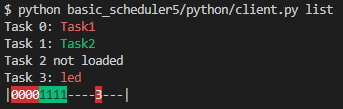
What it shows is:
- There are 4 slots that can be loaded with tasks.
- There are 16 pages of flash memory that the tasks can be put in.
- Currently slots 0, 1, and 3 have tasks loaded with the names “Task1”, “Task2”, and “led”.
- The tasks in red are stopped, and the tasks in green are running.
- The memory occupied by each tasks is show on the bottom with the task’s slot (0-3) taking up a space for each page of flash it occupies.
Here’s a demo of using the client with the scheduler:
While most of this Python code is fairly straightforward CLI and serial interface stuff, the compile_task function is how I ended up relocating the task object files to run at arbitrary flash offsets on the device.
The function does two things. First it does the compilation:
1
2
3
subprocess.call([tool_path + "avr-gcc.exe", "-o", elf_out, object_file, '-nostartfiles', '-Wl,-static',
                f'-Wl,-section-start=.text={section_addr}', f'-Wl,-section-start=.scheduler_funcs=0x800310', '-mmcu=atmega168', '-B',
                'C:\Program Files (x86)\Atmel\Studio\7.0\Packs\atmel\ATmega_DFP\1.6.364\gcc\dev\atmega168'])
Here it is setting the start of the .text section (where the tasks entry point is) to the start of the flash offset the task memory will be written to. In addition it sets the .scheduler_funcs to the offset my scheduler used when it was compiled. This is the RAM offset with a table of system call pointers that the tasks can use. Since this is set here, the tasks wouldn’t need to be recompiled even if I moved this in the scheduler.
The function also does an obj-dump and checks if any symbols are being allocated in RAM. This would detect if the task was written incorrectly and wouldn’t work when running in the scheduler.
Final Thoughts
This was a refreshing project in being able strip away all the levels of abstraction, and write something fairly complicated starting from first principles.
While this code is not suitable for any real world application, I don’t think it would require that much work if there was a real use case. I guess the most likely use would be for being able to update parts of a system while leaving critical functionality running.
Adding a watchdog and making the control protocol more robust would probably be enough to make it usable.