Haunted Doll Keyboard with VUSB
I added a USB cable to a doll which would be detected as a USB keyboard, and give a personality quiz through notepad. The user starts and responds to the doll by pressing “Caps Lock” on their real keyboard.
All my code for this project is in https://github.com/axlan/haunted_doll
Brainstorming
I had mentioned that I made the (Two Keys Wedding Gift Box) as a gift for a college friend’s wedding. Well, I had a second college friend getting married, and I couldn’t restrain my desire to make something a bit weirder. I was still on a bit of a time crunch, and had to set my sights on something achievable.
We had a running joke back in school involving hiding a dollar store baby doll around the apartment. I ended up bringing the doll home at the end of our time together, and it’s been sitting in my parts bin ever since.
I was interested in finding a way for the doll to “talk” in an unusual way. This is sort of inspired by the weird techniques that came out of the spiritualist movement, like ghosts tapping out morse code like signals.
When I was reading about the Digispark USB from my last project, I had noticed that the bootloader worked by having the microcontroller bit bang USB data. There were libraries available to have the chip act as a number of low speed devices. I thought having the doll pretend to be a keyboard would be an interesting solution.
While spoofing a keyboard would be “a” way to send data from the doll to the PC, it would be pretty annoying if it just typed over whatever the person was doing. I wanted to have some way of triggering the doll. I could have done this with a button on the doll, but it turns out that USB keyboards receive data from the PC on which LEDs to light up. This lets the keyboards stay in sync if multiple ones are connected at once. I think I randomly stumbled on this when a when using and external keyboard with a laptop.
Having a Microcontroller Act as a USB Device
USB on Microcontroller Background
For a long time I’ve wanted to better understand the details of how USB works. While this was still a pretty shallow foray into the details, I actually got progressed my understanding at least a little bit.
First a little background on USB. Most people are at least somewhat aware of USB and that it’s gone through different cables and speed iterations (https://en.wikipedia.org/wiki/USB#History). At a super high level generally USB is a way to connect a “device” to a “host”. Being able to be a USB host or device are actually fairly different problems. An MCU acting as a USB host, might be able to have a USB drive plugged into it and read the data, while an MCU acting as a USB device might be able to show up as a USB drive when plugged into a computer. Here I’ll be talking about adding USB device capabilities to an MCU.
The USB specification of USB interfaces is very generic. You can specify entirely custom devices that require special drivers, or you can conform to some pre-specified interfaces and use the built in drivers. In this case I’m trying to conform to the human interface device (HID) standard for a keyboard. Even here’s there’s some room for customization, but I need at least the minimal functionality of sending keypresses, modifier keys, and receiving the LEDs to light. Basically this entails making the device correctly advertise its capabilities and handling the input and output packets this specifies.
The next thing to understand is where the USB logic is implemented. On most Arduinos and other integration boards, the main MCU itself doesn’t actually do anything related to USB. Some boards use a dedicated USB to serial chip as seen here: https://www.arduino.cc/en/uploads/Main/arduino-duemilanove-schematic.pdf. In this example the FT232RL acts as the USB device. My preferred IoT board the NodeMCU uses a similar approach. These chips are pretty neat since they can provide relatively high speed data transfers from the device to a PC without needing much MCU code. I’ve used them several times with FPGAs where it can greatly simplify getting data off the device.
Some newer Arduinos use a small second microcontroller to act the USB device https://content.arduino.cc/assets/UNO-TH_Rev3e_sch.pdf. How does this microcontroller do it? In the case of the Arduino Uno it uses a ATmega16U2. This microcontroller has built in USB capabilities. Most of the low level USB stack is implemented in the MCU silicon, so once again you can avoid having the software deal with low level USB. You do need to implement the higher level USB functionality, but the MCU has a lot of flexibility allowing the higher level code to implement a custom USB device, or one of the standards. The USB Arduino framework https://github.com/NicoHood/HID/ targets AVR chips with this functionality.
Both of these approaches offload the heavy lifting of the USB to hardware. The Digispark on the other hand needs to do everything in software. In looking into this previously I had stumbled across the VUSB project. This is an embedded cross platform library that implements the low level USB functionality with a lot of configurability to allow it to run on many different platforms. Just as with the microcontrollers with built in USB functionality, you still need to implement the logic for the actual device on top of this framework.
Getting the Digispark to Act as a Keyboard
Being unfamiliar with the details of USB, I’ve found it pretty hard to get started with VUSB on previous attempts. However, in this case I had some good examples to work from. First off, Digisparks has some Arduino libraries. The code here was a bit messier then I’d expect and also didn’t implement capturing the Caps Lock state.
I ended going through this page https://www.obdev.at/products/vusb/projects.html of VUSB projects and actually found one that had a somewhat similar idea to me. https://github.com/7enderhead/kbdwtchdg is the code for a project that has USB connected ATtiny (the same chip as the Digispark) act as a watchdog for a piece of software running on a PC. It waits for the PC to press the Caps Lock key, and if none are received for some timeout, it will type a sequence over it’s keyboard interface to restart the software. It’s quite clever, though I’m not sure this would ever be a practical solution. Within this project was the exact code I needed to implement a full VUSB keyboard. I started with the code from the Digispark library and took the changes I’d need to VUSB configurations from this project.
This mostly entailed editing the usbconfig.h file to set USB_CFG_IMPLEMENT_FN_WRITE to 1 to enable the functionality to read data from the PC, and increasing the size of USB_CFG_HID_REPORT_DESCRIPTOR_LENGTH so it was big enough for the descriptor of the more full featured keyboard.
The only other changes were updating DigiKeyboard.h with the new descriptor and actually capturing the new led status being sent.
One thing I noted is that pretty much none of these libraries has been updated in the last five years. I guess this isn’t surprising since you can cheaply get MCUs like the ATmega16U2 that are much better solutions. However, I was glad to have an excuse to dig into this area.
Making the UI
Most of coding this project was to actually make the interface between the user and the doll. Since this is an extremely resource constrained system (512 byte RAM, 6012 bytes flash), I knew I would need to be careful with how I was storing and manipulating strings. Early on I realized that using almost any Arduino framework functions would eat up a huge amount of the flash and RAM, so I had to write my own.
The main optimization I needed to worry about was storing all the text in PROGMEM. Normally the variables the program is using need to be loaded into RAM, but the PROGMEM macro allows you to load them straight from flash. See this Arduino documentation for a more in depth explanation.
I decided to structure the program as a series of menus. Each “screen” would print out a message, then offer a series of choices to the user. The user could then go through the menu options which would highlight the selected option. Confirming an option would bring up a new “screen” with it’s own set of choices. I wrote a python script that made editing these menus easier.
I probably made this a lot more complicated then it needed to be. As part of the python generation, each menu could also specify callbacks. These handle the external actions that might be triggered by selecting a menu item (like exiting, or updating the quiz answers).
Initially I made full use of Num Lock, Scroll Lock, and Caps Lock for navigating forward and backwards and selecting options. However, I realized that many keyboards may not actually have all these keys. Instead, I moved to just using Caps Lock. The interface would be started up by double tapping Caps Lock. A single click would move to the next option, and double tapping would select. Exit would be a menu option on each screen that would put the device back into its idle state.
The current selection would be shown by using SHIFT to highlight the text. This assumes a fairly basic text editor that doesn’t manipulate things too much. It would also be totally thrown off if the user clicks on the editor, or types anything.
Aside, from some silly text, the main “application” is a personality quiz like the “Which game of thrones character are you?” sort of thing. It determines what kind of haunted doll you would be. I quickly realized I didn’t have enough memory to store the text of a “real” quiz. So I picked a small set of questions and mapped them randomly to lists of adjectives and nouns to generate a unique doll based on the 64 possible combinations of answers.
I did a pass at refactoring to try to modularize the code a bit better. This actually increased the flash usage by a hundred bytes or so. This probably would have been reduced if I had stuck to doing everything in a more C like style, but I decided it was good enough, since it still fit. Since my project uses over 99% of the flash, I’d probably need to do this rewrite if I wanted to do anything more extensive.
Additional Challenges
From the start I was fighting against RAM and flash usage. However, it was crazy that include a call that triggered an Arduino framework print statement used thousands of bytes of flash over directly writing a loop over a character string. Even just setting an LED used over a hundred bytes for what boils down to only a couple opcodes if done optimally. I mostly just used trial and error, commenting out portions of the code to figure out what I needed to cut or optimize. Fortunately, VUSB appears to be written very efficiently, and I didn’t need to worry there much. I also chose to keep the size of my writing fairly modest to avoid needing to go too deep into the optimization rabbit hole.
As I mentioned before, the menu working properly depends on the behavior of the text editor. If I had a specific OS+editor combo I was targeting I would have been able to be more efficient by using keyboard shortcuts for copy/paste and “select all”. I left the most compatible implementation in place which can be pretty slow. There’s a delay between each key stroke so it can take a few seconds to move the cursor all the way across the screen. I thought this accentuated the whole “haunted” aesthetic.
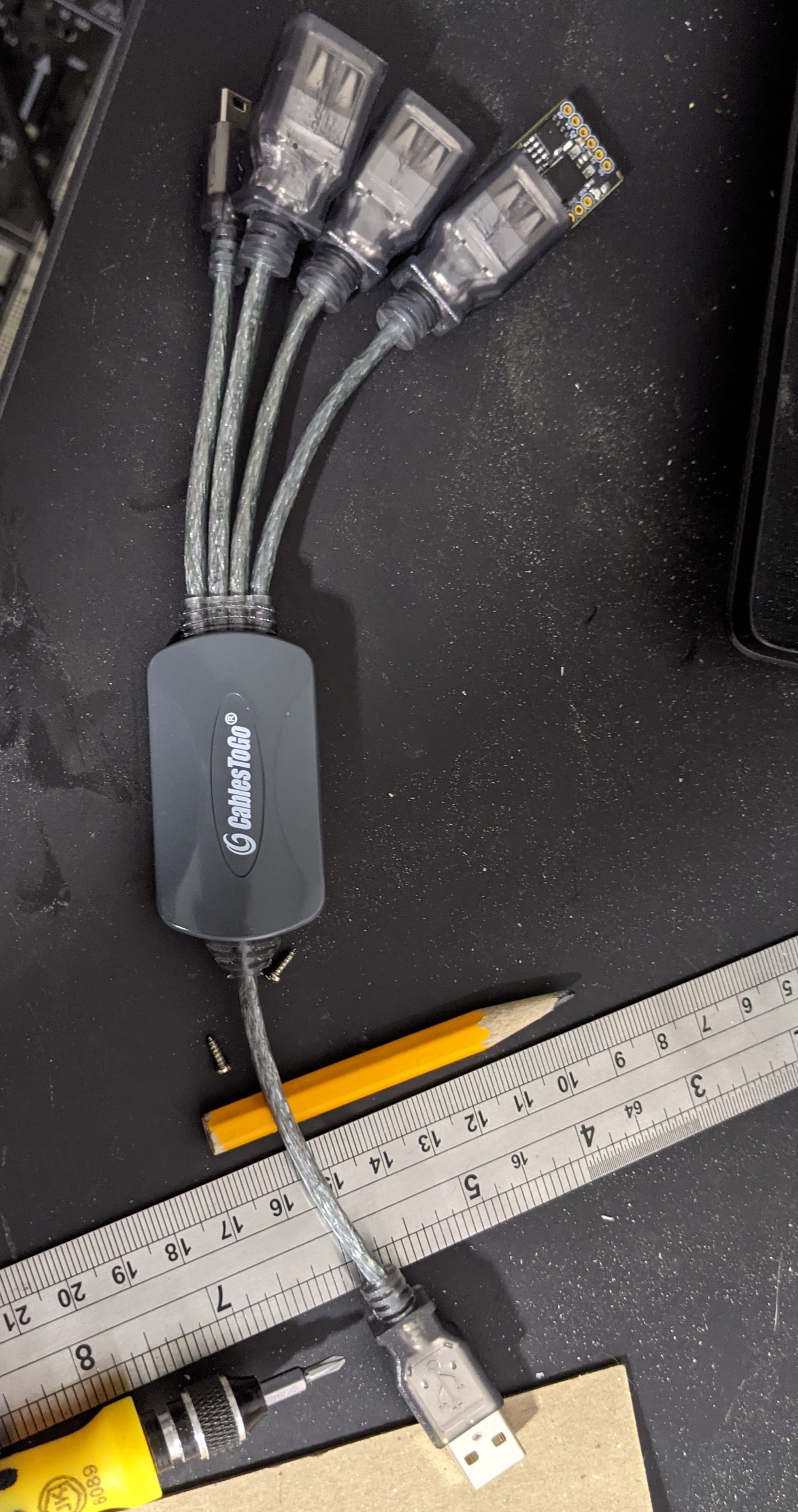
Aside from the software challenges, it turns out the Digispark USB emulation isn’t bullet proof electrically either. I had trouble getting it to be detected on some PC’s. It seems like USB 3 interfaces might be a particular issue: https://arduino.stackexchange.com/questions/63137/digispark-micro-attiny85-not-working-on-macbook-pro-2016. I got around this by finding an old USB hub I could use. All the PC’s I tested with were happy connecting through the hub.
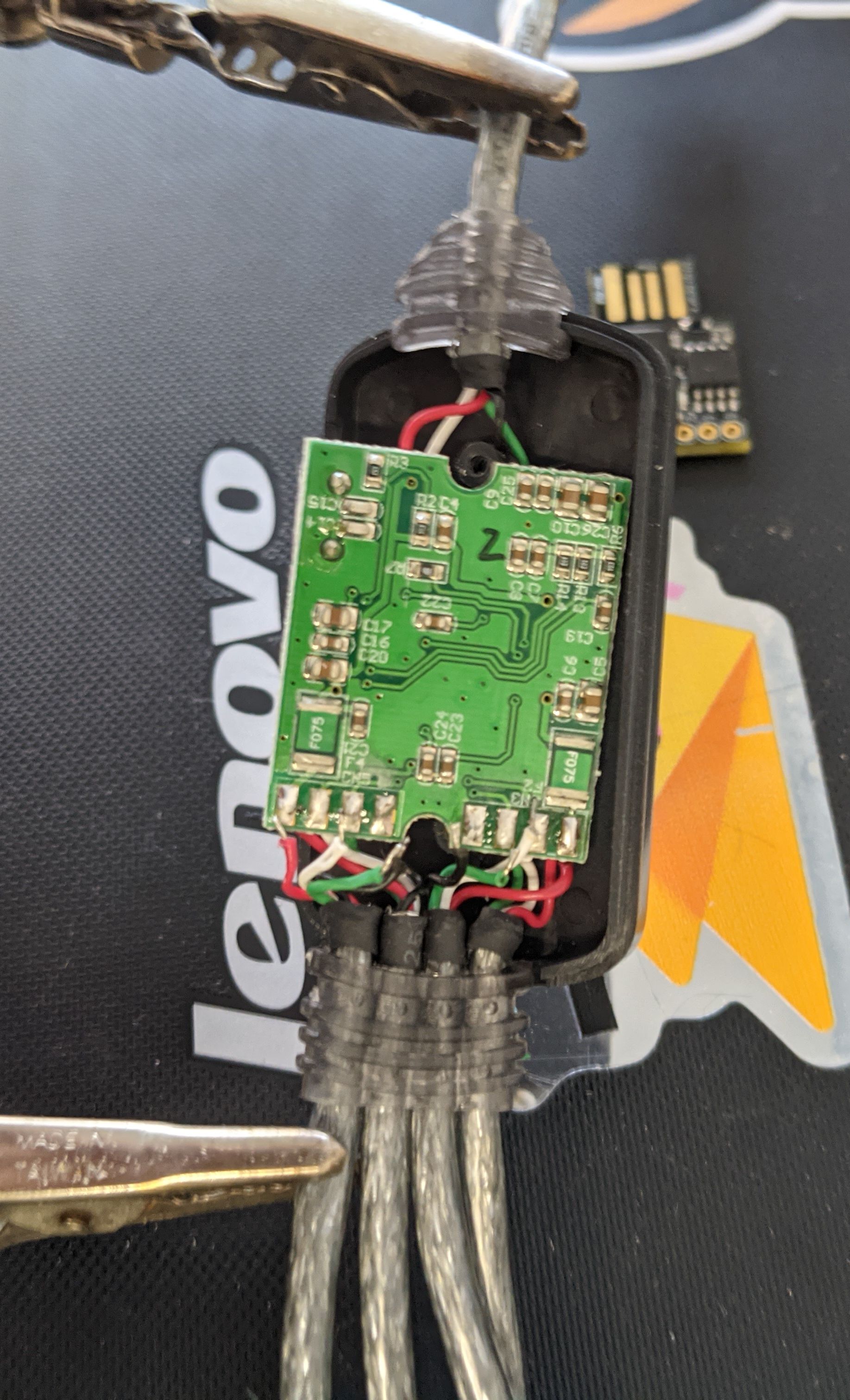
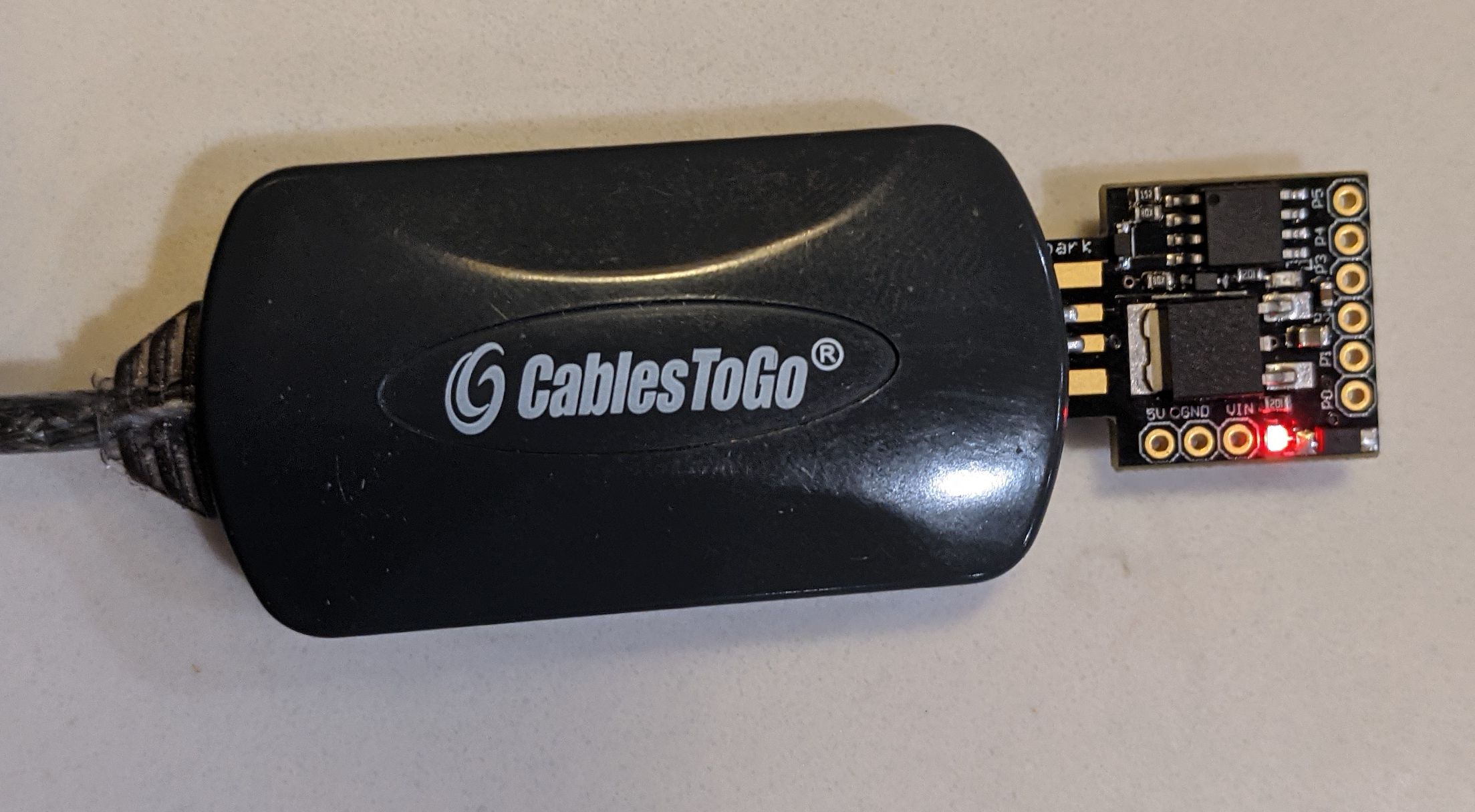
Here’s the hub before and after soldering on the Digispark:
The last and most unexpected issue was testing this on OSX. When you connect a USB keyboard the OS brings up a configuration wizard. It prompts you to press a series of keys then select the keyboard type. This totally interferes with my application. If I was just targeting OSX I could get around this by entering the keys once or on a hardware button, but it would be a pretty big pain.
Putting it Together
The last step was integrating the hub with the Digispark into the doll. The hub was just the right size to fit in the doll, but there wan’t enough space unless I was able to get the Digispark into the doll’s head. The neck was too narrow, so I needed to cut a slot for it to fit.

All that was left was to sew it back together. Maria helped with that. The main effort was making the USB cable more closely resemble an umbilical cord than a penis.
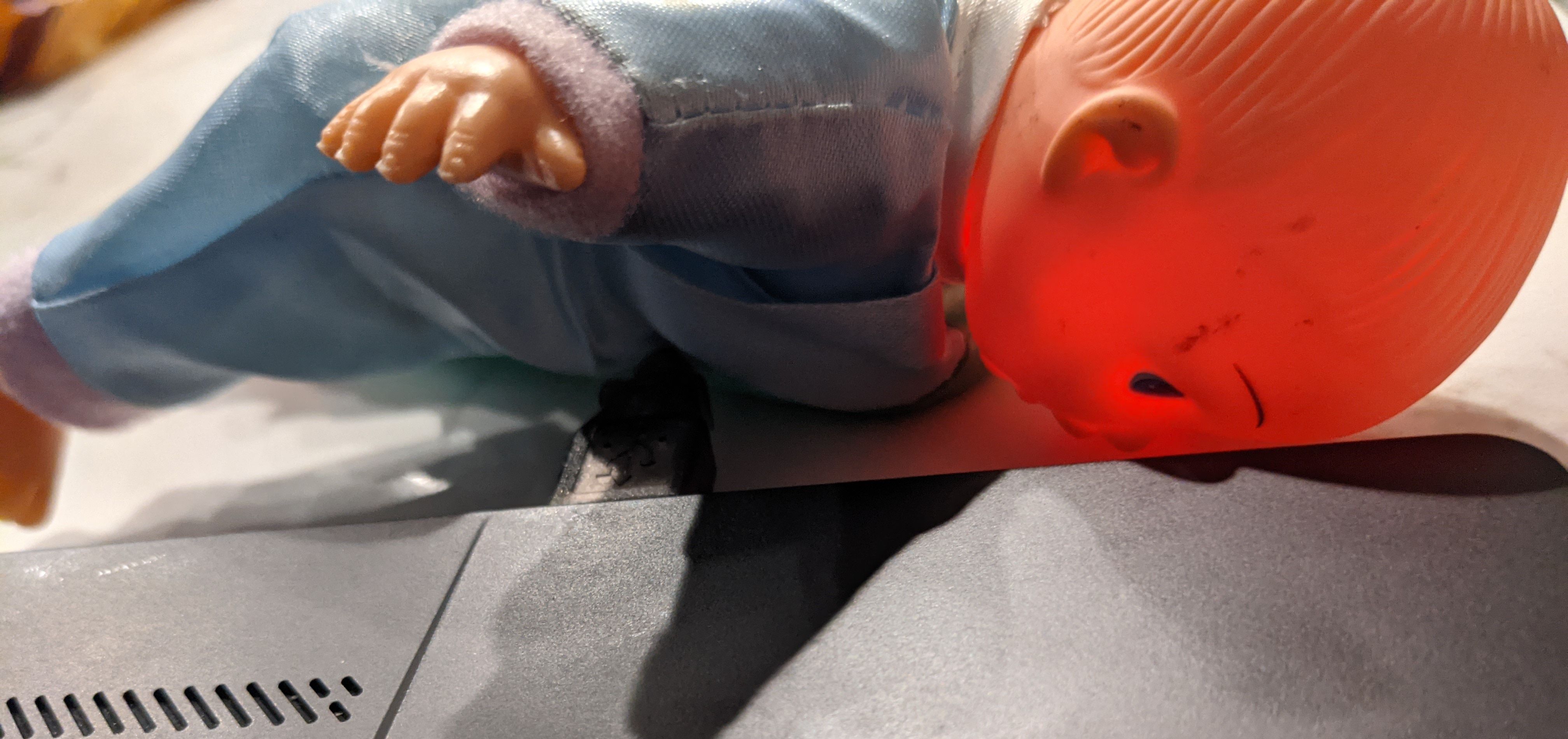
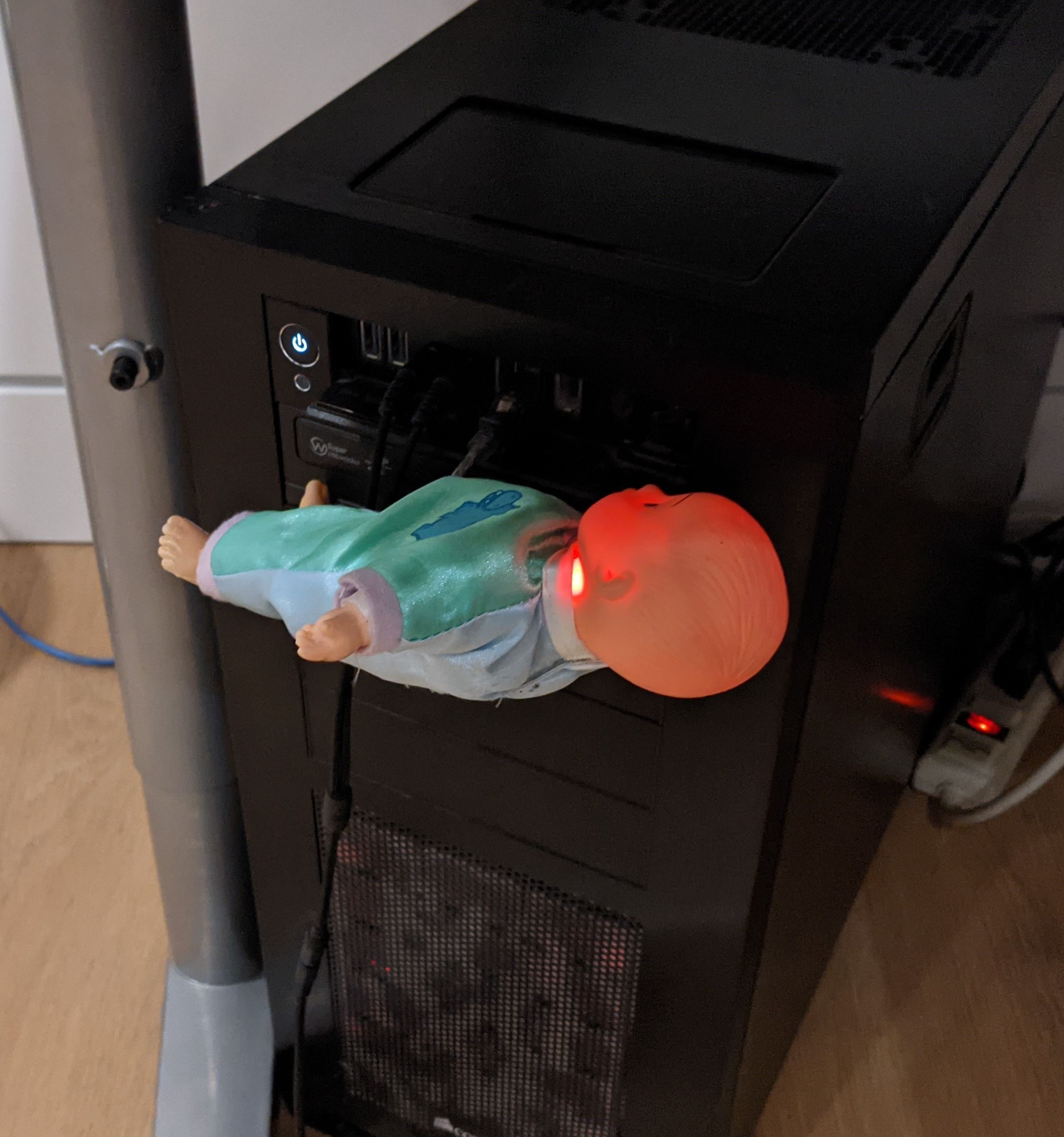
It looks suitably creepy when connected.