Two Keys Wedding Gift Box
I made a decorated box that opens when a magnet key is placed on both sides.
A demo of the finished project to start with:
Brainstorming
As I switched jobs I had a little bit of time to plan a project, but knew I probably would be pretty distracted during the execution. I decided to make a wedding gift with a little more polish then my usual stuff. Initially, I was thinking of all sorts of interesting projects like a solar powered pyramid that would blink out the wedding date in morse code, a reverse geocache, or a treasure box that only opens when touched by fingers with two different pulse rates.
In the end, I decided to go with something a bit more straightforward. My wife reminded me that since it’s a wedding gift, so it should probably be less of a science experiment.
I decided to make a locked treasure box sort of like this blast from the past Magic Gift Box or even Hidden Book Safe. The main difference here is that I’d try to make it more polished and robust since I wouldn’t be around to fix it if it breaks at some point.
The first thing I wanted to figure out, was how to more reliably make an electronic latch. Previously I’d used a servo to hook a a latch into place, or slide a wooden peg. This works fine, but always seemed like the most fragile part of the project. I started looking at electronic locks and latches, and eventually found some reasonably priced electronic cabinet locks that seemed like they would be perfect. Since they were 12V I used this as a constraint for the rest of the parts I’d select.
Initially, I thought I might be able to get away without programable logic. At a high level all the box was doing was taking a logical AND of two sensors and triggering the latch when they were both active. Unfortunately, the latch needed to be pulsed and could be damaged if it was held in the triggered state. This is completely doable, but requires several components https://electronics.stackexchange.com/questions/211024/how-to-generate-edge-triggered-pulse. In the end I decided to go with the simplest microcontroller I could find, which was a cheap clone of the Digispark USB. This board was perfect since it has a built in 12V to 5V voltage regulator which I’d need for the sensors.
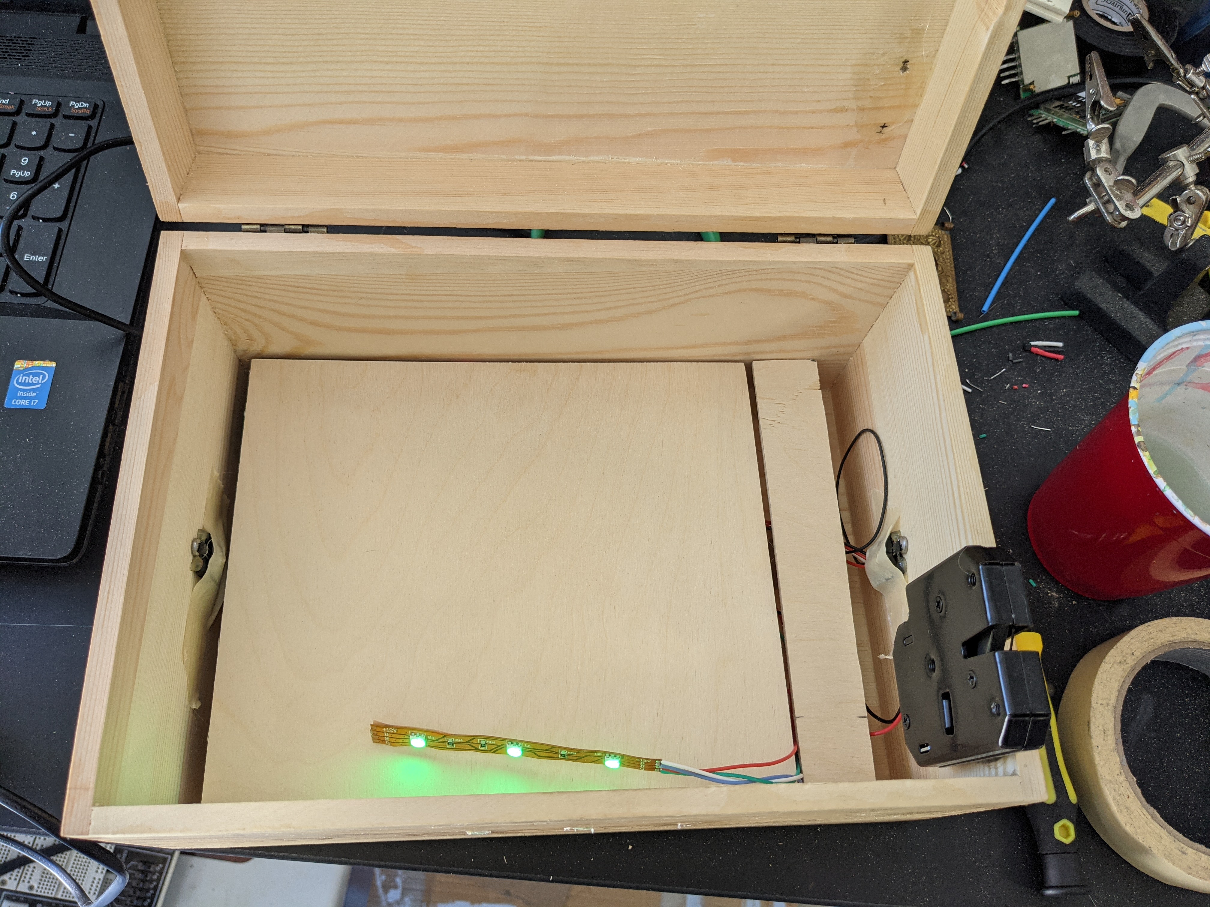
Since I was using a MCU, I could add some light effects. I had some old 12V RGB LED lighting strips lying around. They weren’t the digital addressable ones I’ve used so often so they would be a bit harder to work with, but it was a good opportunity to used them. The strip is somewhat modular, so I cut off a 3 LED section.
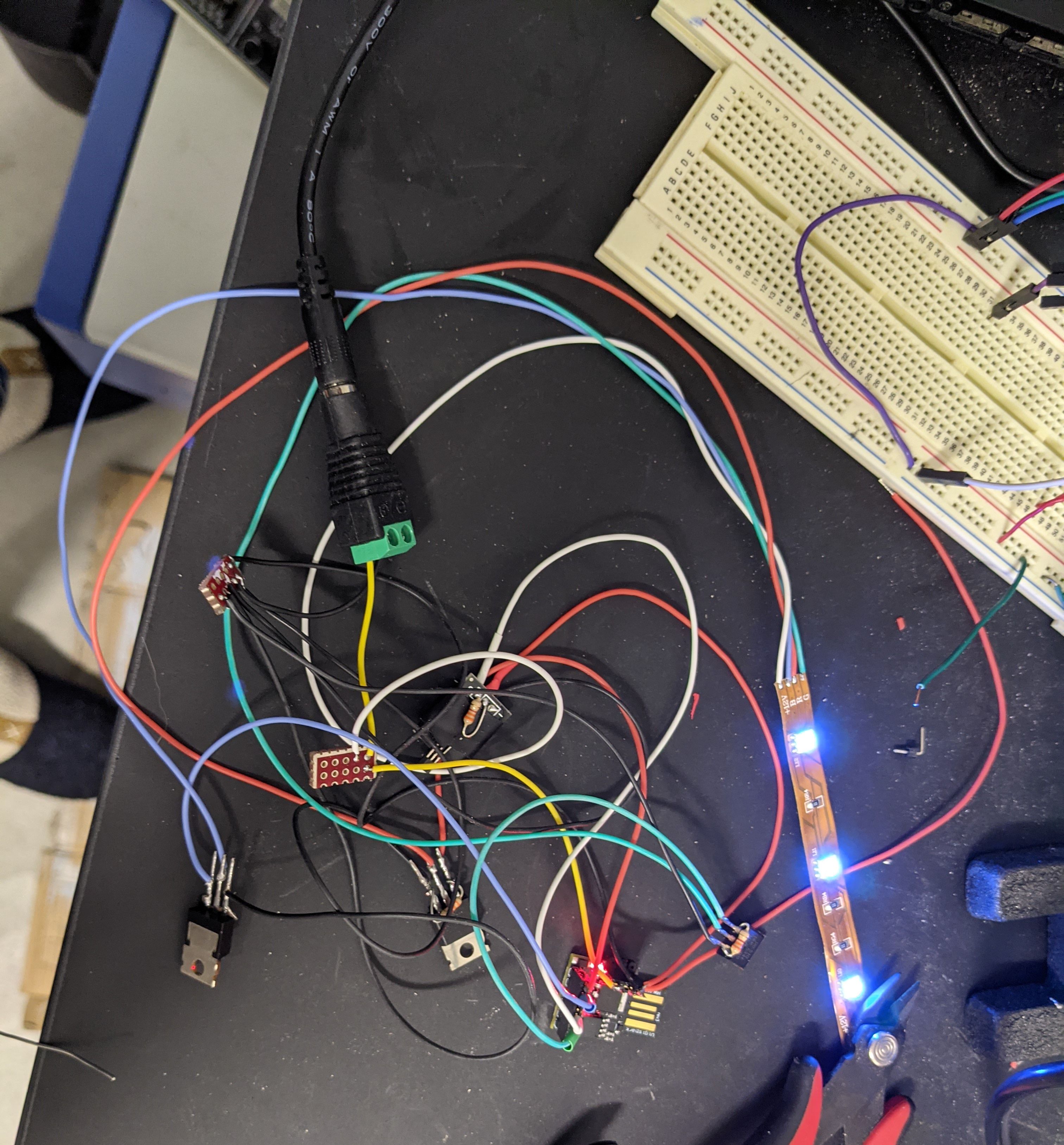
Experimenting with the components
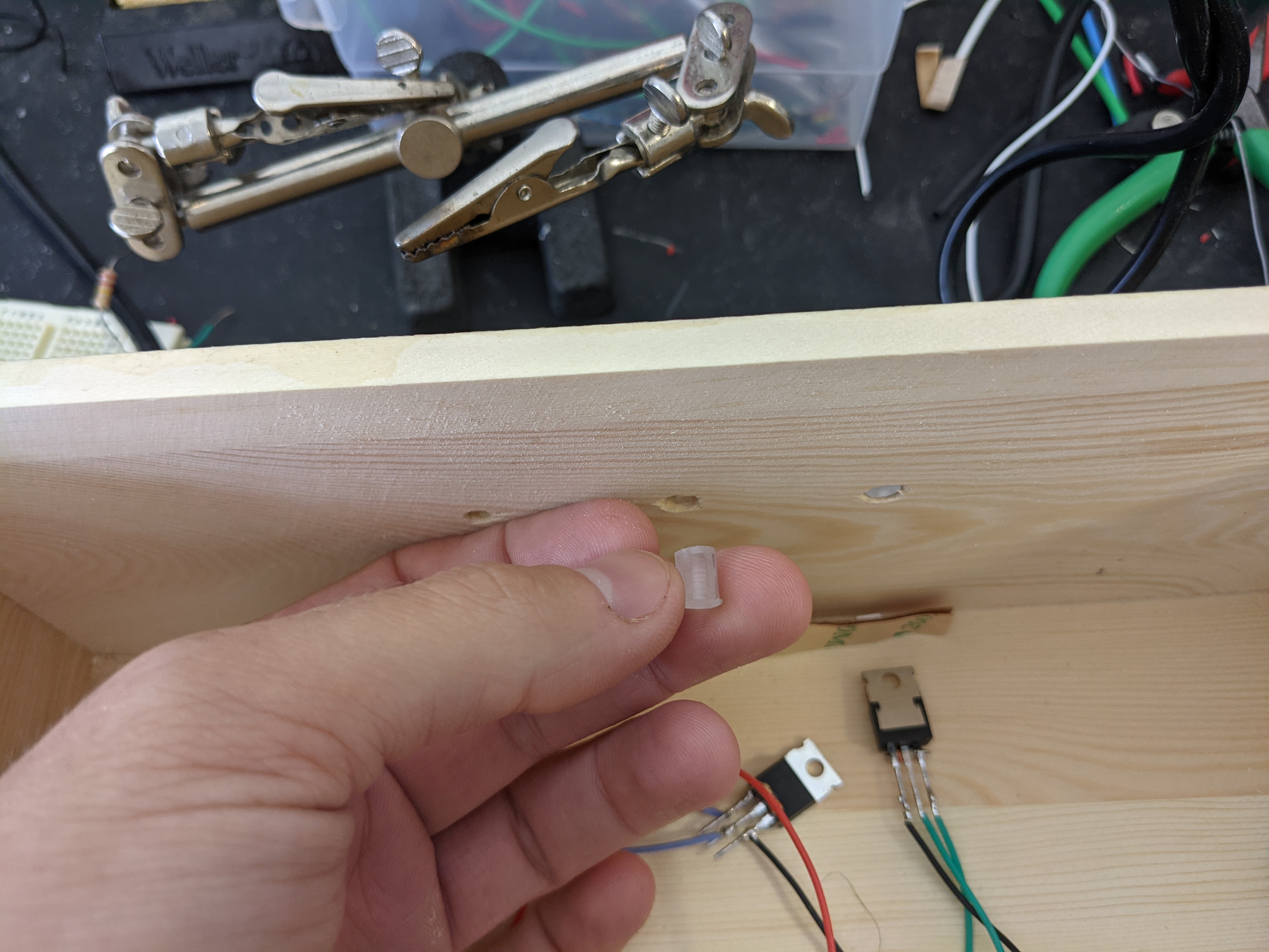
I knew I wouldn’t be able to drive the LED’s and latch motor directly from the MCU, so I looked at my parts bin for what transistors I had handy. I had some power switching IRF510, which seemed like they would be perfect for controlling both the LED’s and motor. However in testing, I found that when I applied 5V as the gate voltage, the drain to source voltage was insufficient to trigger the latch. The transistor datasheet seems to suggest it was a close thing, but there’s no arguing with reality. Fortunately, I also had a relay board I could use.
Making the Box
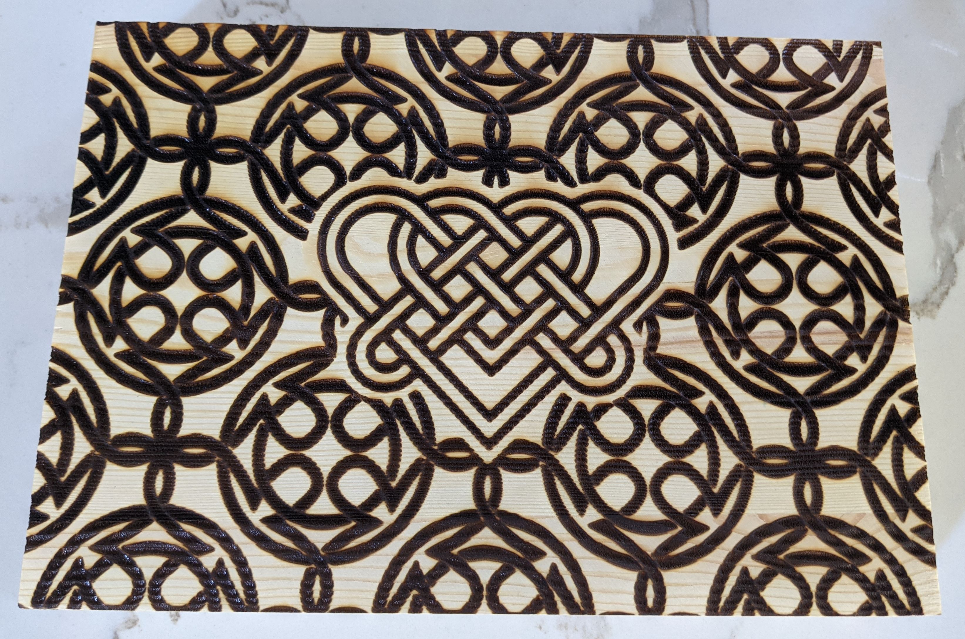
The Lid and Keys
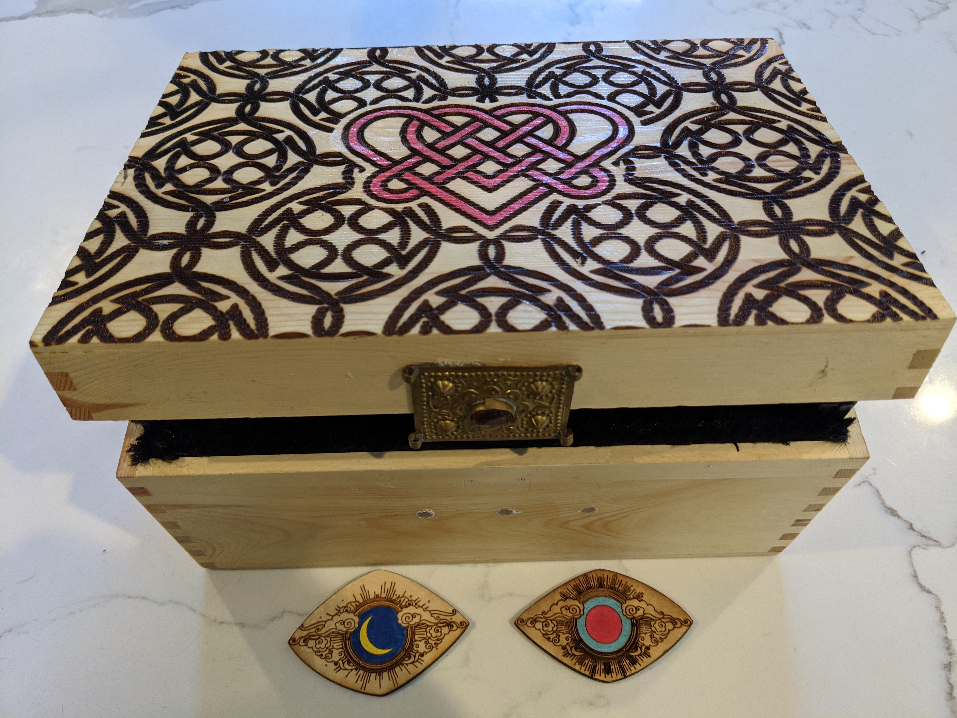
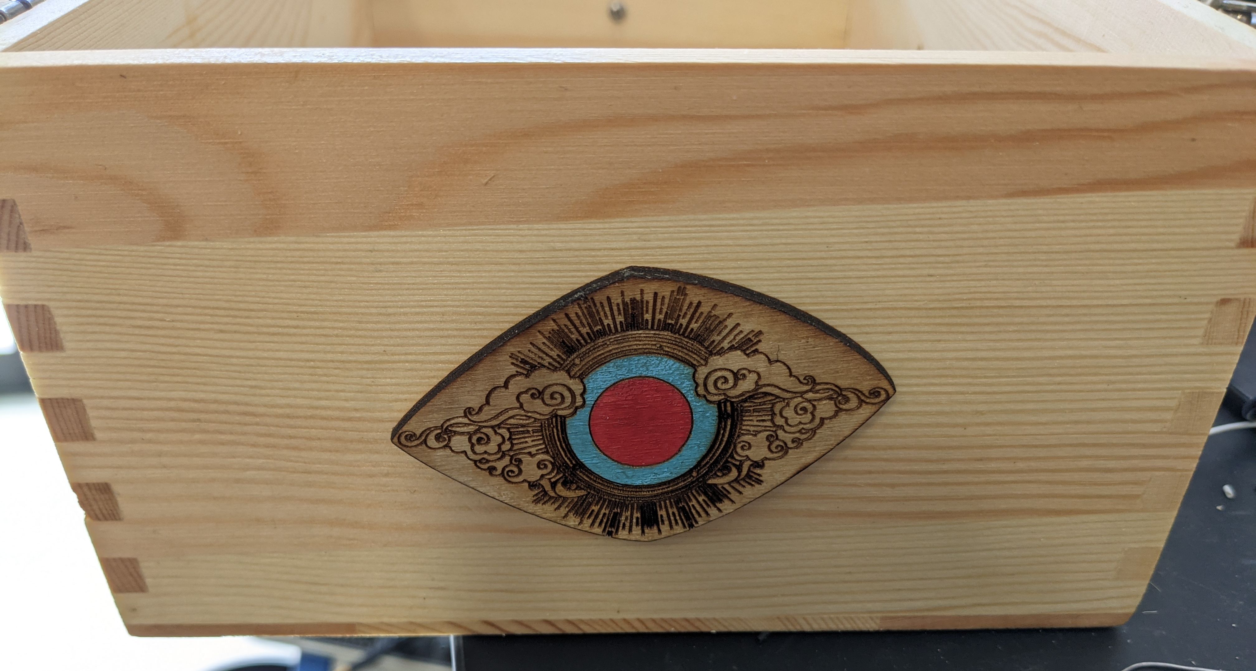
The laser cutter is my go to for decorating, but engraving the box had some challenges. I’m familiar enough with vector art at this point, that I was able to find some workable designs without too much trouble. I went with a celtic knot pattern for the top of the box, and I masked in a heart knot into the center. For the keys, I went with a sun/moon theme.
When I went to engrave the box, the length and width fit in without issue. but it was far too tall to fit in the machine. At some point I really should tear out the metal plate that blocks me from using the machines full depth, but it would be a pretty significant endeavor. By taking the hinges off, I could fit just the lid in. However, it was tall enough that its surface was above the laser’s focal point. This actually turned out OK, since the pattern I was burning was fairly wide, without a lot of detail.
The keys pretty much worked without any issue, and I painted some accents and sealed the whole thing with modge podge.
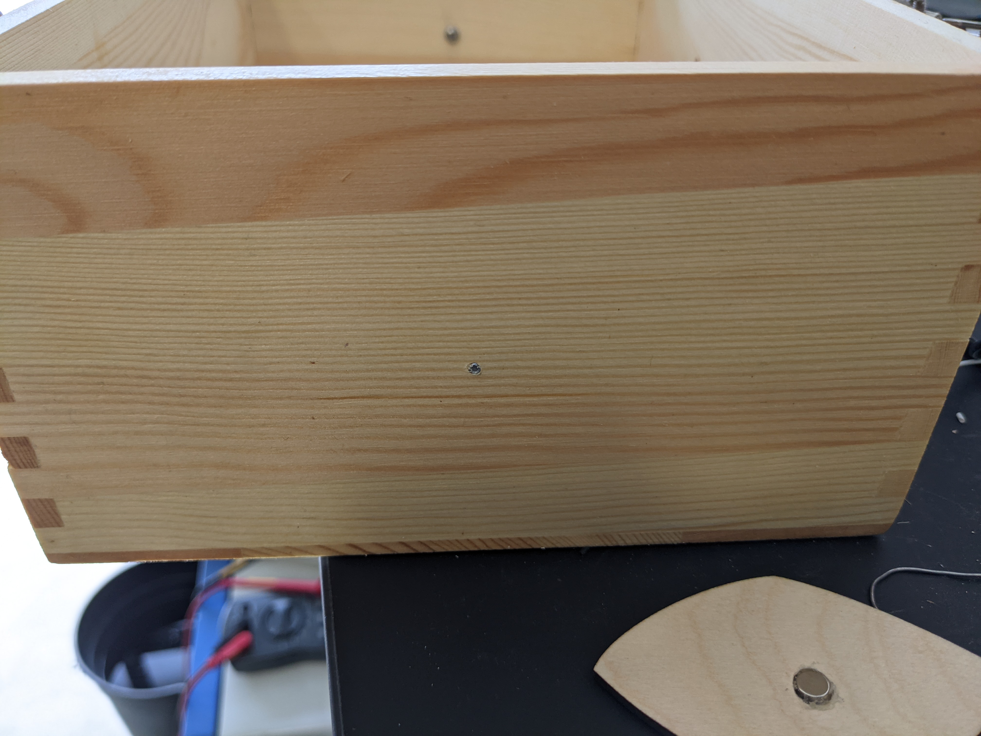
In my initial tests, it seemed like the HALL sensors wouldn’t work through the sides of the box. I also wanted something for the keys to stick to. I solved this by driving in screws that just pierced the outside of the box.
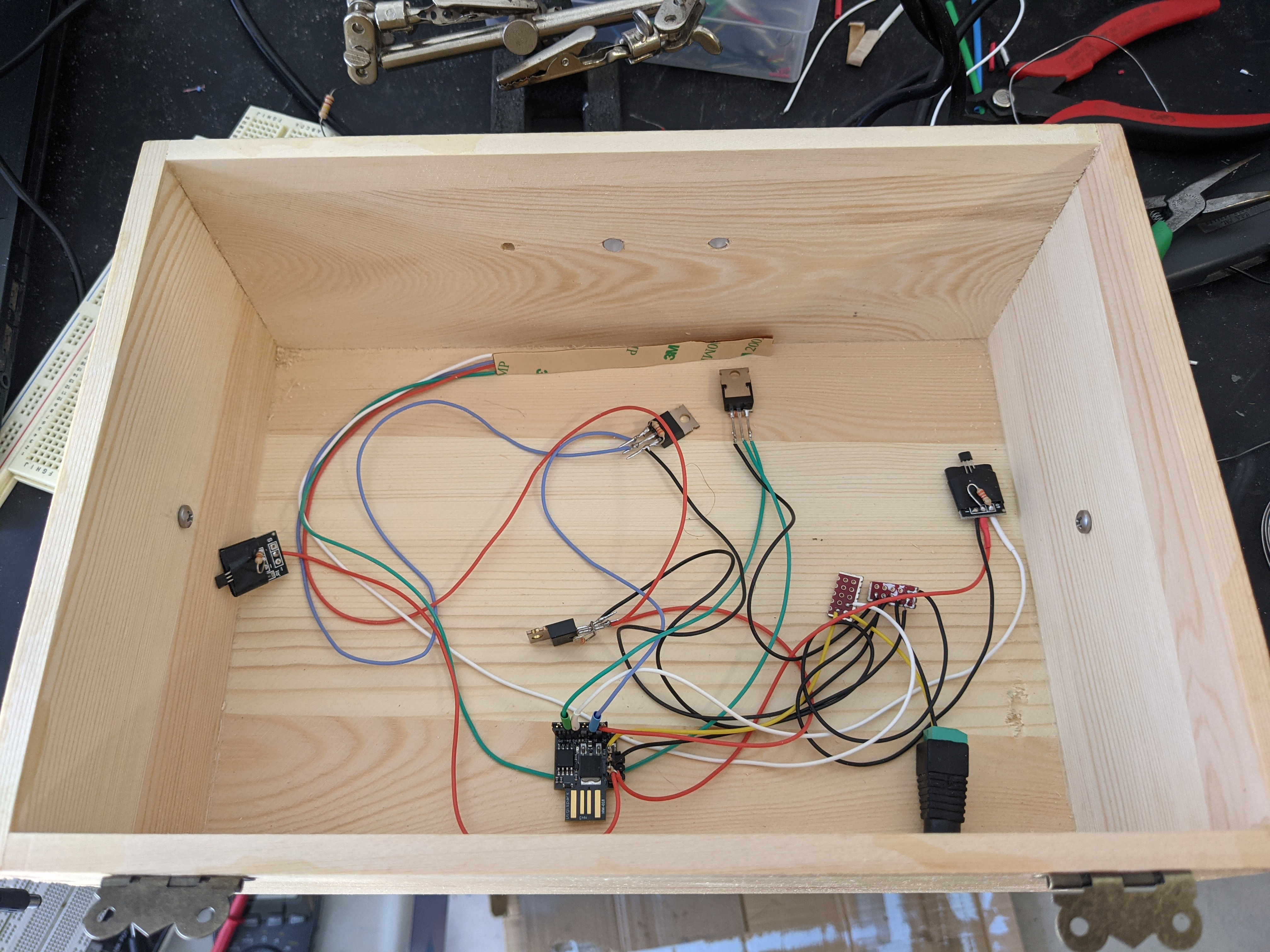
Putting Together the Electronics
While the electronics were fairly simple, I did need to figure out a few things by trial and error.
I created a PlatformIO project develop the MCU code: https://github.com/axlan/two-key-box
I found I needed to add pullups to the HALL sensors, though I’m fairly certain this should be able to be done with IO configuration in the MCU. The Digispark is a fairly interesting platform. It uses a bootloader that makes it emulated a USB device. You need to install a special driver on your development machine, but it lets you program it over USB without requiring any additional components. PlatformIO handles figuring out how to do the actual programming at least. The only issue here is that the chip has a 5 second delay while the bootloader waits to see if it’s being programmed. This can be turned off, but between this and the next issue, I didn’t want to risk not having any way to reprogram the chip.
I wanted to make some simple LED patterns that changed depending on which keys were in place. While this is simple enough, controlling the color and brightness at the same time is not trivial when dealing with LED’s. In a case of massive overkill, I used the FastLED library to convert from hue/saturation/value (HSV), to RGB values. See the libraries explanation of their color space https://github.com/FastLED/FastLED/wiki/FastLED-HSV-Colors.
The Digispark breaks out all 6 of the ATiny85’s 6 IO pins. I was going to use 3 for controlling the LED colors, 2 for the HALL sensors, and 1 for the switch relay. As I was testing the functionality, I realized that the last pin (PIN5) wasn’t working properly. A quick search revealed that the ATiny uses this last pin as a reset pin for programming by default. The clone Digispark boards don’t change the programmable fuse that would enable this pin to be used for IO. Fortunately, I had an AVR ISP I could use to reprogram the fuse. This guide gives an overview of the process, and uses another arduino, instead of an AVR ISP to do the programming.
Instead of using AVR Dude, I used the programming GUI in Microchip Studio https://microchipdeveloper.com/8avr:avrfuses which makes it very clear that you’re setting the correct values. The one issue here is that I would no longer be able to reprogram the bootloader, and I wouldn’t be able to turn off the delay.
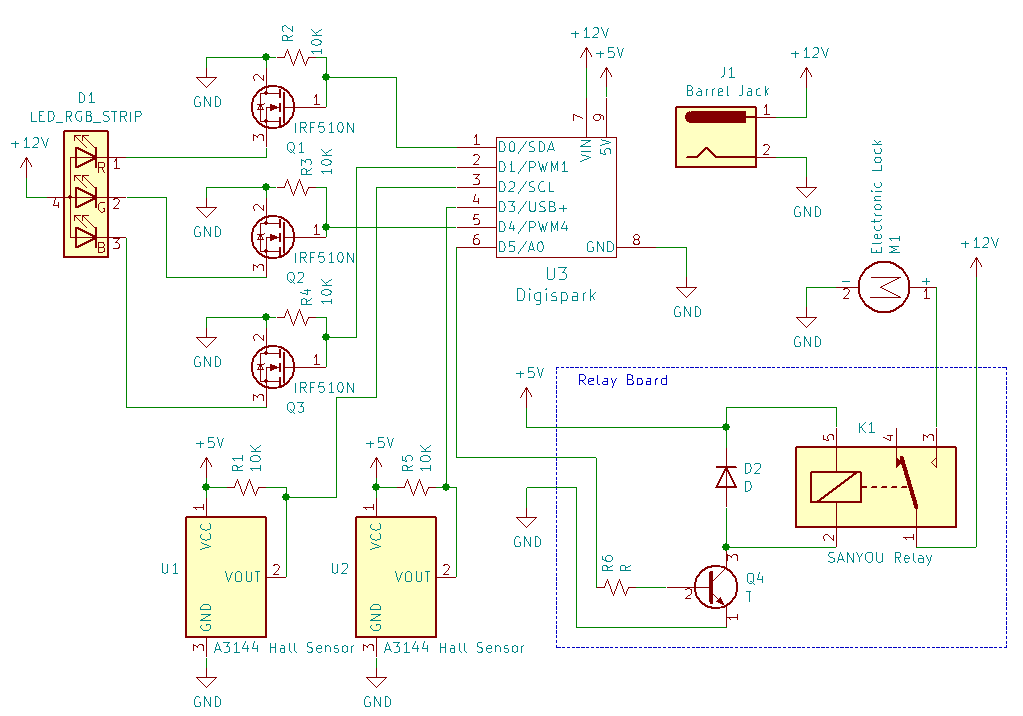
Here’s the final schematic I ended up with:
Putting it All Together
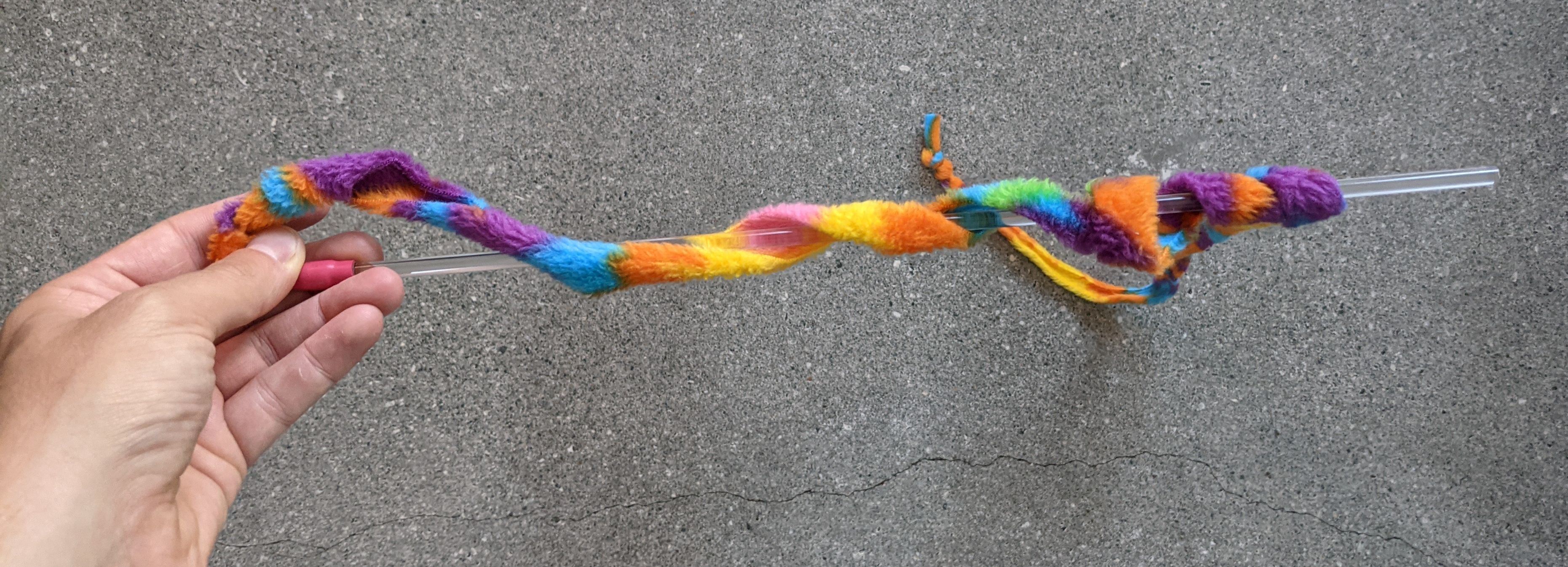
To let the light shine through the box I wanted to cut cylinders of plastic to act as light pipes. After looking around I found a cat toy that I could cut pieces off of.
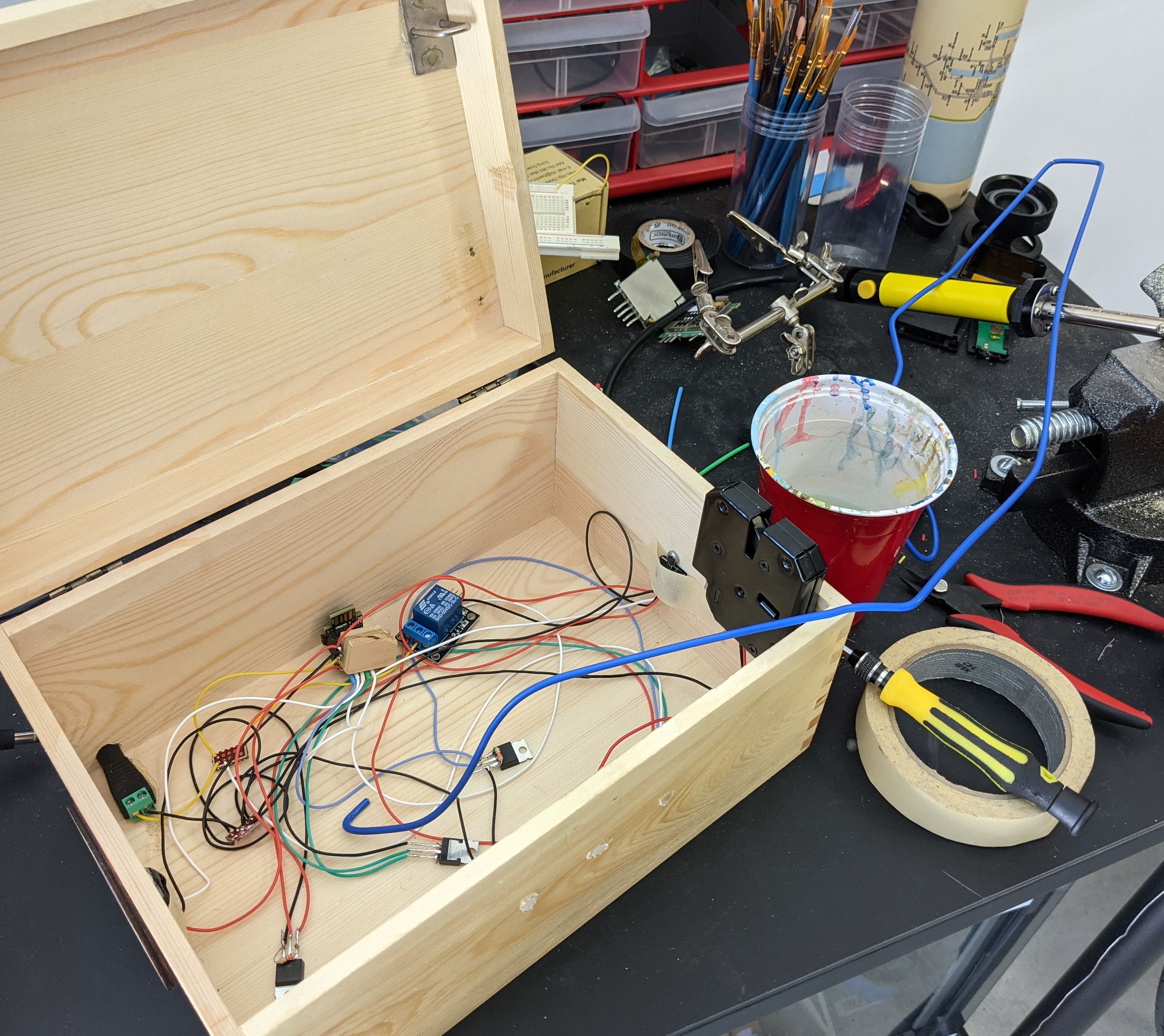
Since the points in the box I was connecting to were spread out across the box, I decided to hide them under a false bottom. I cut out little wooden blocks to act as supports.
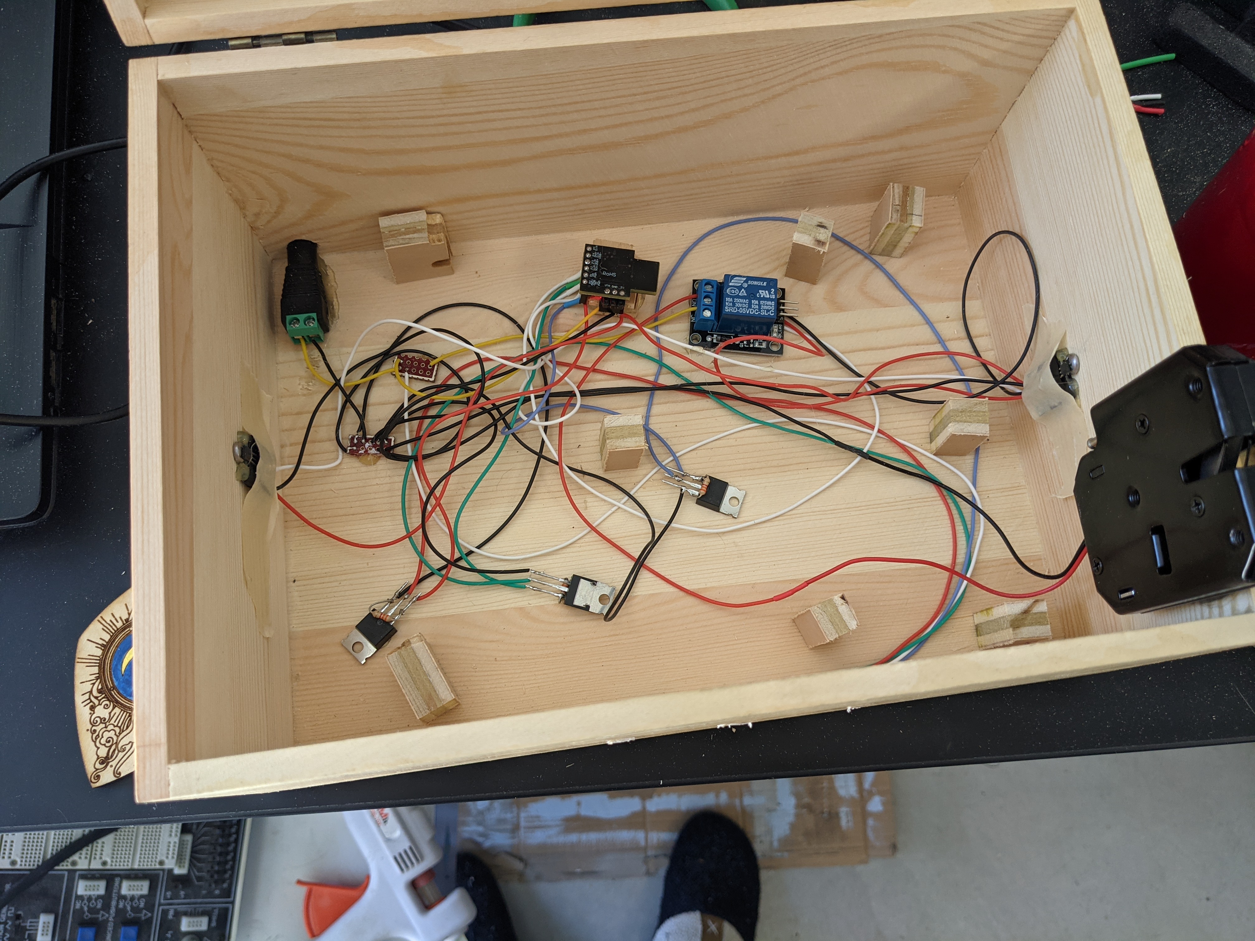
I had a surprisingly hard time mounting the latch and hook into the box. At first I didn’t compensate for the arc the hook would swing as it lifted with the lid. Next I didn’t take into account that the hook needed to go deeper into the latch then it normally sat to initially lock in place. I had to keep using a heat gun to melt the glue I used to try again.
The next mistake I made, was accidentally closing the box without the relay fully wired up. While I might have been able to melt the glue through the box, or get a little more space by taking the hinges off, I managed to catch the manual release using a bent coat hanger.
With these blunders out of the way, I was able to get it all put together.
For lack of a better solution, I anchored the pieces inside the box with hot glue.
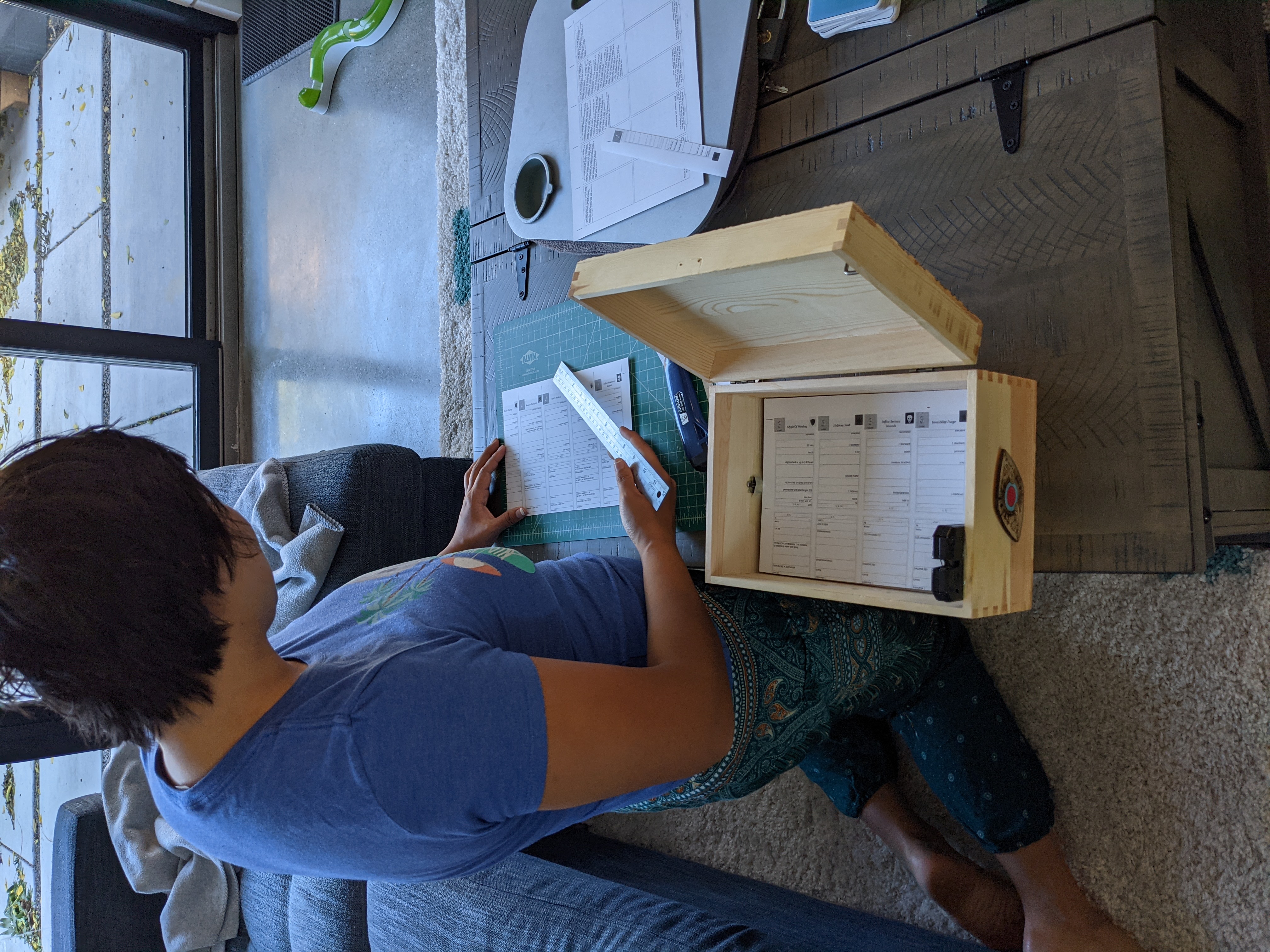
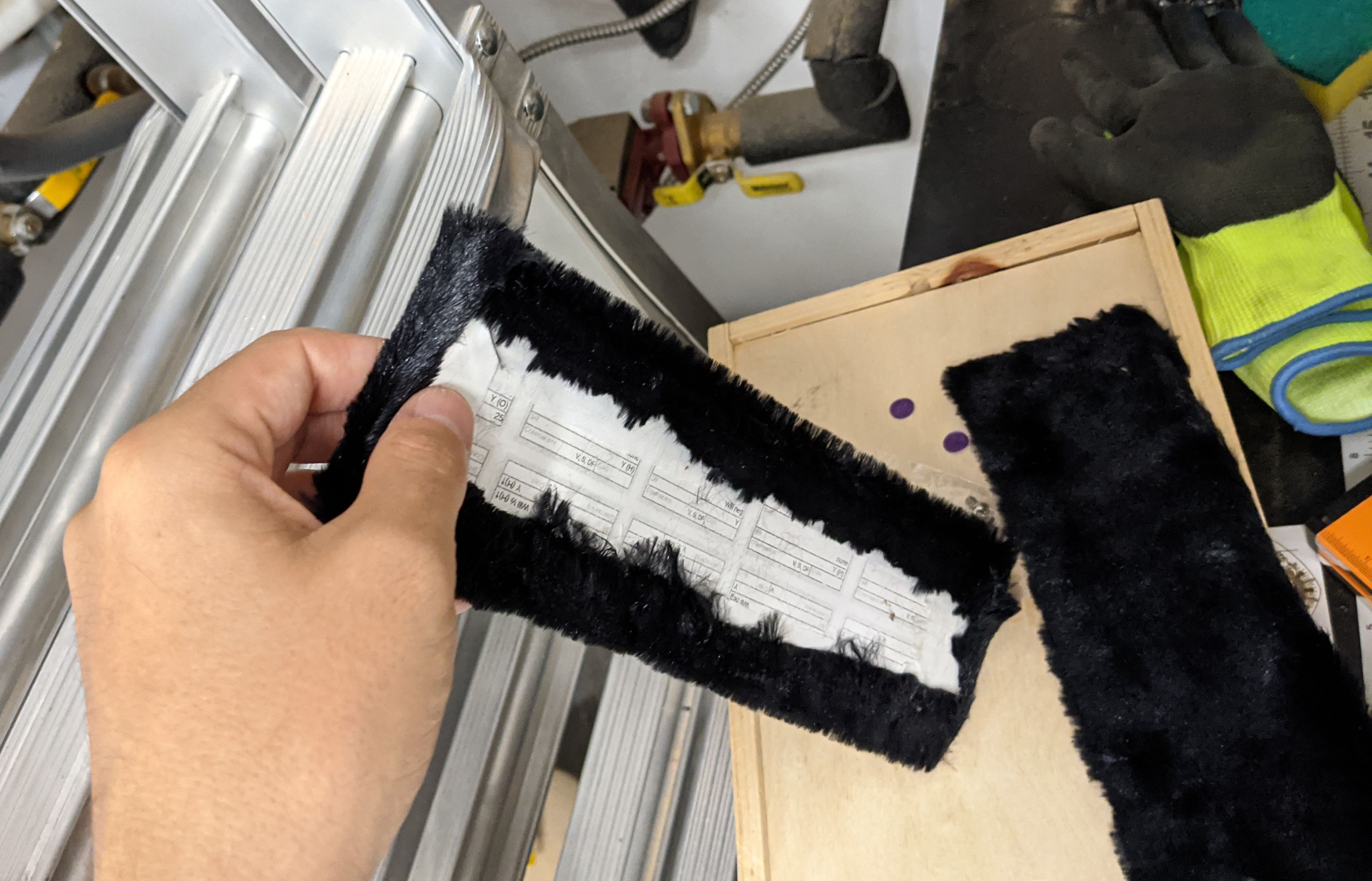
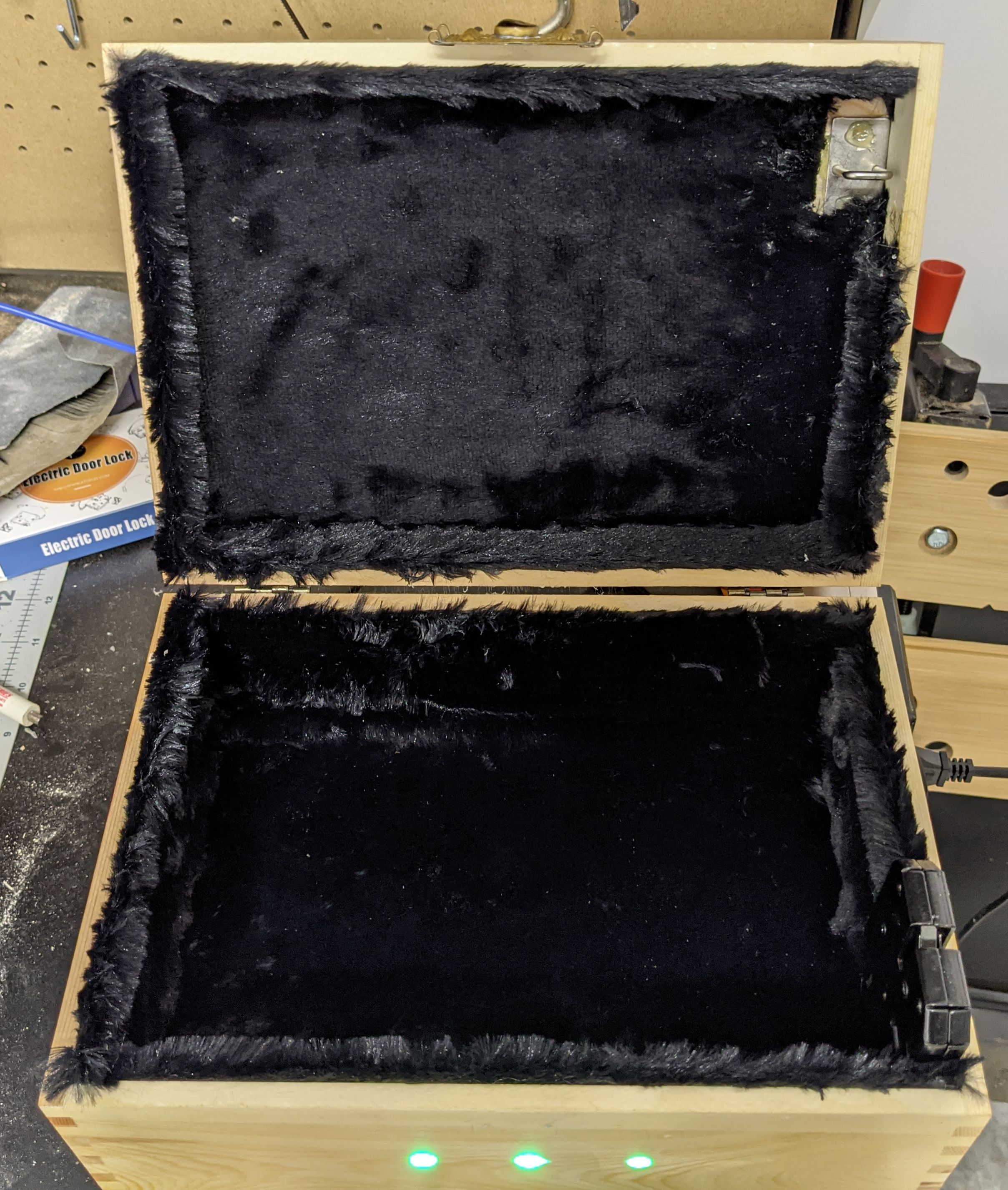
The next step was lining the inside. Maria had some left over fur from a different project and found this video for creating panels to cover the box.
This went pretty smoothly and soon the whole thing was done. I’m very happy with how it turned out, and I hope it holds up well.