
Playing Around With JTAG
While this wasn’t a particularly novel project, I spent some time trying to better familiarize myself with how the JTAG interface works.
One topic of system design that I’ve always been especially interested in is processor bootstrapping. Probably not surprisingly since I recently did a similar project looking at the x86 boot process. One aspect of bringup is how to interface with a processor if it isn’t able to boot from non-volatile memory. Either because it’s storage was corrupted, or hasn’t been initialized. This is where I was introduced to JTAG. Using it as a tool to load bare metal programs into RAM to recover embedded devices or do early development.
I’ve always used JTAG as a bit of a black box though. I knew it could be used to arbitrarily interact with memory, and control processor execution. I’ve also seen it used to allow the host computer to run GDB on the connected processor. What’s always confused me about JTAG is that these features are not inherent in the protocol.
It’s only when I’ve read about it in the context of reverse engineering that I had a better understanding of what’s actually going on. The blog post (https://wrongbaud.github.io/jtag-hdd/) does a good job explaining the details of the actual interface and has some good further reading. The issue is that the standard is very open, and there’s a wide amount of variation in the features supported and even in the connectors and pins.
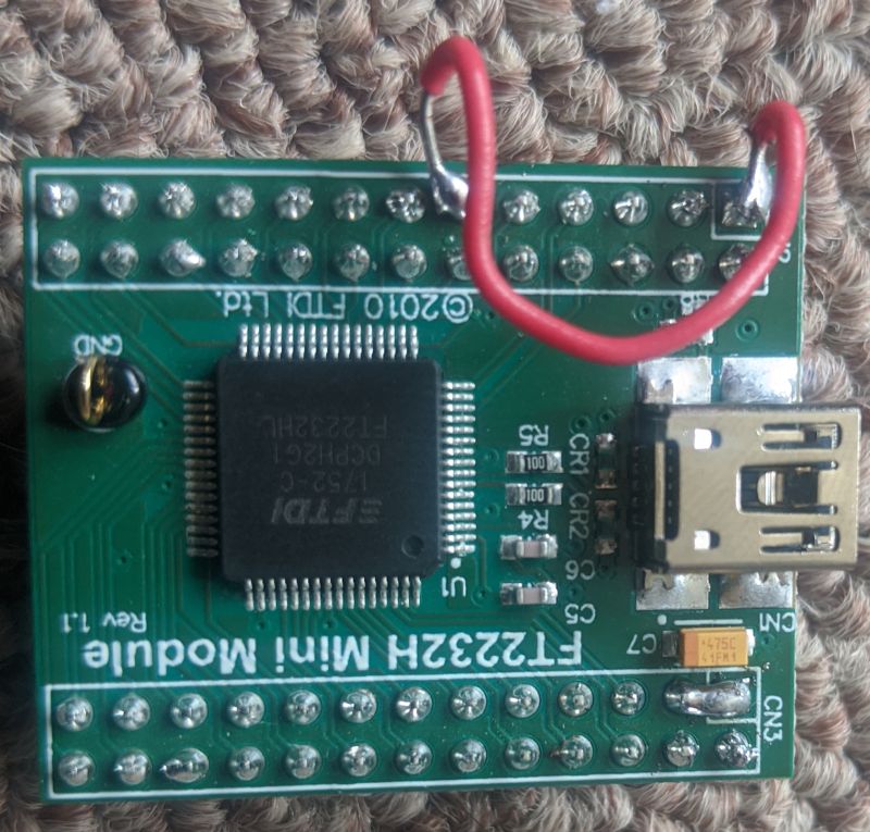
To try to get a better intuition of what’s how JTAG works I wanted to connect a generic JTAG adapter to one of the embedded processors I had lying around. I decided to go with the FT2232H Mini Module since it’s cheap and can be used for a variety of other applications as well. The first thing I needed to do was figure out how the modules power distribution worked. There are no built in jumpers, so I had to do some soldering to connect the Vcc and IO power.
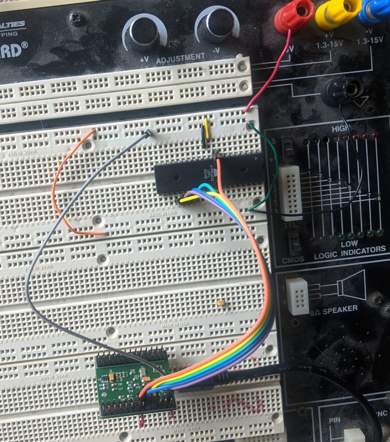
I thought starting with a microcontroller would be easier, but I was surprised to find JTAG isn’t supported accross the board on Atmel products. The atmega328p commonly found in Arduinos supports a proprietary alternative (debugWIRE). I found I had an Atmega32 that supported JTAG so I tried to connect to it with a minimal setup.
For the host side I used OpenOCD. It’s a pretty complicated tool, and I had some mixed luck trying to follow tutorials and the manuals. There’s a decent amount of information out there, but there’s so many combinations of adapters and processors, it can be hard to figure out what’s relevant.
Unfortunately, I was unable to detect the Atmel. Without having a dev board, there was a lot that could potentially be wrong, either in my OpenOCD config, or in the bread board setup.
I decided to try to move to a platform that would have more support, so I set up a connection to a RaspberryPi. This article describes how to configure the RaspPi GPIO pins to accept JTAG connections. I ended up with the following mapping between the RaspPi and the FT2232H module.
1
2
3
4
5
6
# ADBUS0 – CN2-7  – TCK   – PC2 – 24 – YELLOW
# ADBUS1 – CN2-10 – TDI   – PC5 – 27 – GREEN
# ADBUS2 – CN2-9  – TDO   – PC4 – 26 – BLUE
# ADBUS3 – CN2-12 – TMS   – PC3 – 25 – PURPLE
# ADBUS5 – CN2-13 – Reset – NA  – 9  – ORANGE
# GND    – CN2-2  – NA    – NA  – NA – GREY
In the section on manually connecting the RaspPi JTAG in this article, it describes how to run a script to set the GPIO states so that they will listen for the JTAG connection.
I updated my RaspPi and compiled and ran the C code they gave.
To run OpenOCD I tried to use the config they provided for the MiniModule (https://github.com/ntfreak/openocd/blob/master/tcl/interface/ftdi/minimodule.cfg) and combine it with the config from this article
Once again though I wasn’t able to detect the processor. At this point I connected a scope to see what was hapenning.
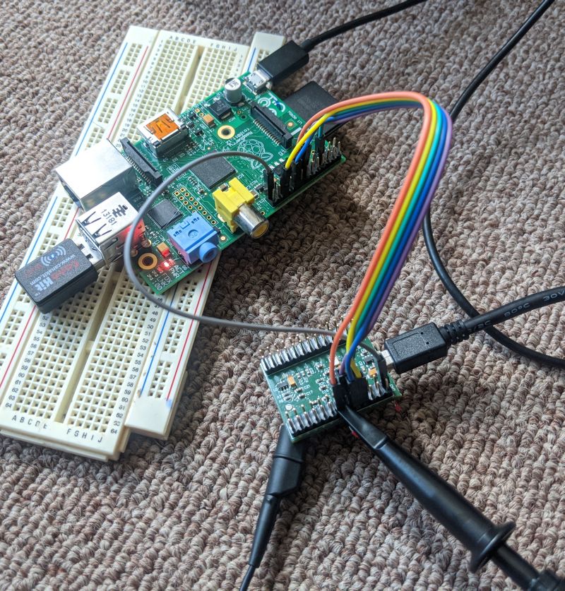
Amazingly, connected the scope fixed it. As long as the scope was attached to the the reset pin things worked and I was able detect the RaspPi over JTAG. Eventually I realized that for my combination of processor and adapter I needed to specify reset_config trst_only in the OpenOCD config. I ended up with the following combined config:
1
2
3
4
5
6
7
8
9
10
11
12
13
14
15
16
17
18
19
20
21
22
23
24
25
26
27
28
29
30
31
32
33
34
interface ftdi
ftdi_device_desc "FT2232H MiniModule"
ftdi_vid_pid 0x0403 0x6010

# Every pin set as high impedance except TCK, TDI, TDO and TMS
ftdi_layout_init 0x0008 0x000b

# nSRST defined on pin CN2-13 of the MiniModule (pin ADBUS5 [AD5] on the FT2232H chip)
# This choice is arbitrary. Use other GPIO pin if desired.
ftdi_layout_signal nTRST -data 0x0020 -oe 0x0020

transport select jtag

adapter_khz 1000
adapter_nsrst_delay 400
reset_config trst_only

if { [info exists CHIPNAME] } {
set _CHIPNAME $CHIPNAME
} else {
set _CHIPNAME rspi
}

if { [info exists CPU_TAPID ] } {
set _CPU_TAPID $CPU_TAPID
} else {
set _CPU_TAPID 0x07b7617F
}

jtag newtap $_CHIPNAME arm -irlen 5 -expected-id $_CPU_TAPID

set _TARGETNAME $_CHIPNAME.arm
target create $_TARGETNAME arm11 -chain-position $_TARGETNAME
rspi.arm configure -event gdb-attach { halt }
I was so overjoyed that I decided to pause for awhile.
The main take away is that I now understand why generic JTAG tools are so rare. Like a lot of things in low level processor control, there’s a lot more variance between devices then I expected. There’s lot of trial and error if you’re not using a combination of tools and software specific to the environment.