Icosahedron Travel Globe
Well it’s been awhile since we’ve been able to travel, so to feel better I decided to make a memento to the big trip Maria and I went on last year. I decided to go with an interactive 20 sided “globe”.
Here’s a demo of it in action:
(Thanks Maria for being the camera operator!)
I think I first saw a 20 sided globe done on Adam Savage’s Youtube channel https://www.youtube.com/watch?v=Fef_lS6nm70, which linked to a Make Magazine article: https://makezine.com/projects/laser-cut-dymaxion-globe/. The Dymaxion map projection was always an interesting engineering solution to the map projection problem, and since I had a laser cutter, I thought this would be a great project to take advantage of it.
Hardware Build
The first challenge of the project was the tedium of cutting this on the 8”x8” wood pieces that fit into my laser cutter. I broke up the original file into 10 pieces. Each piece of wood would have two triangles making up a diamond across the diagonal.

You can see the files in https://drive.google.com/drive/folders/10ju8Ssd7WkMYr3nucr-UNkvh5fo6_8JP
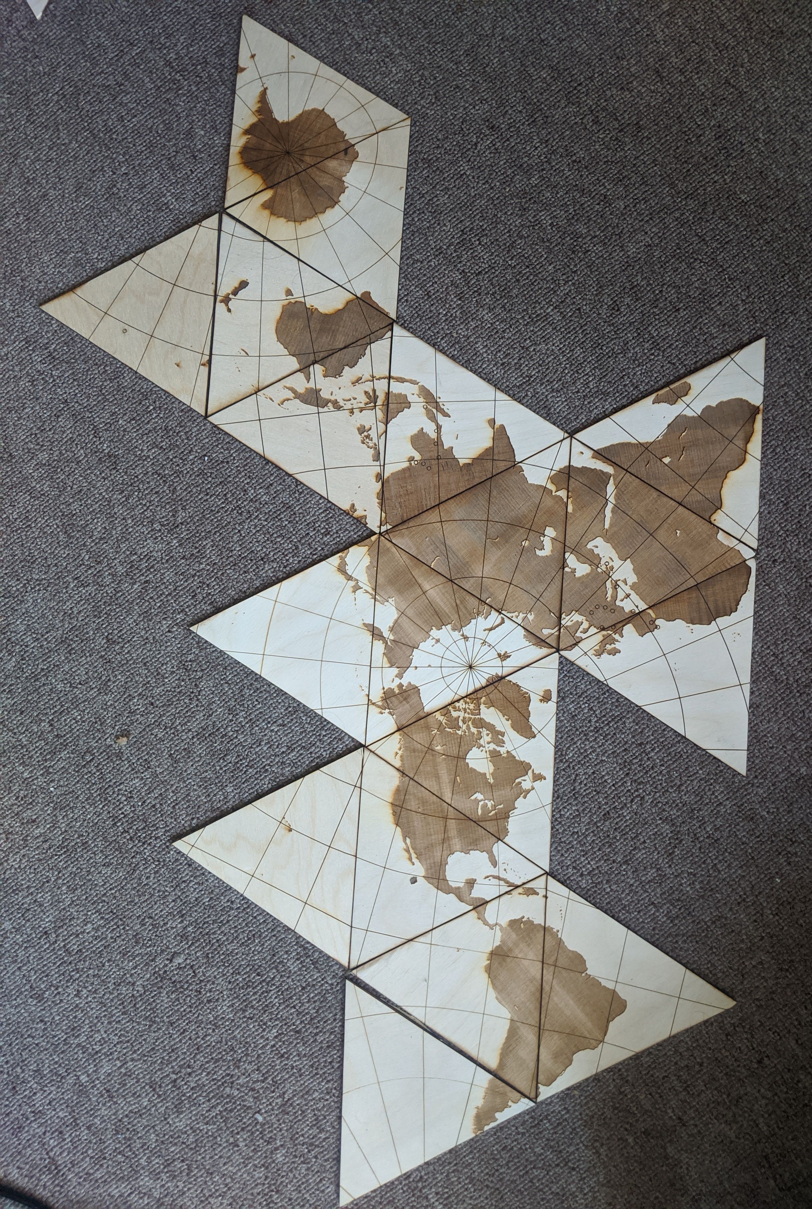
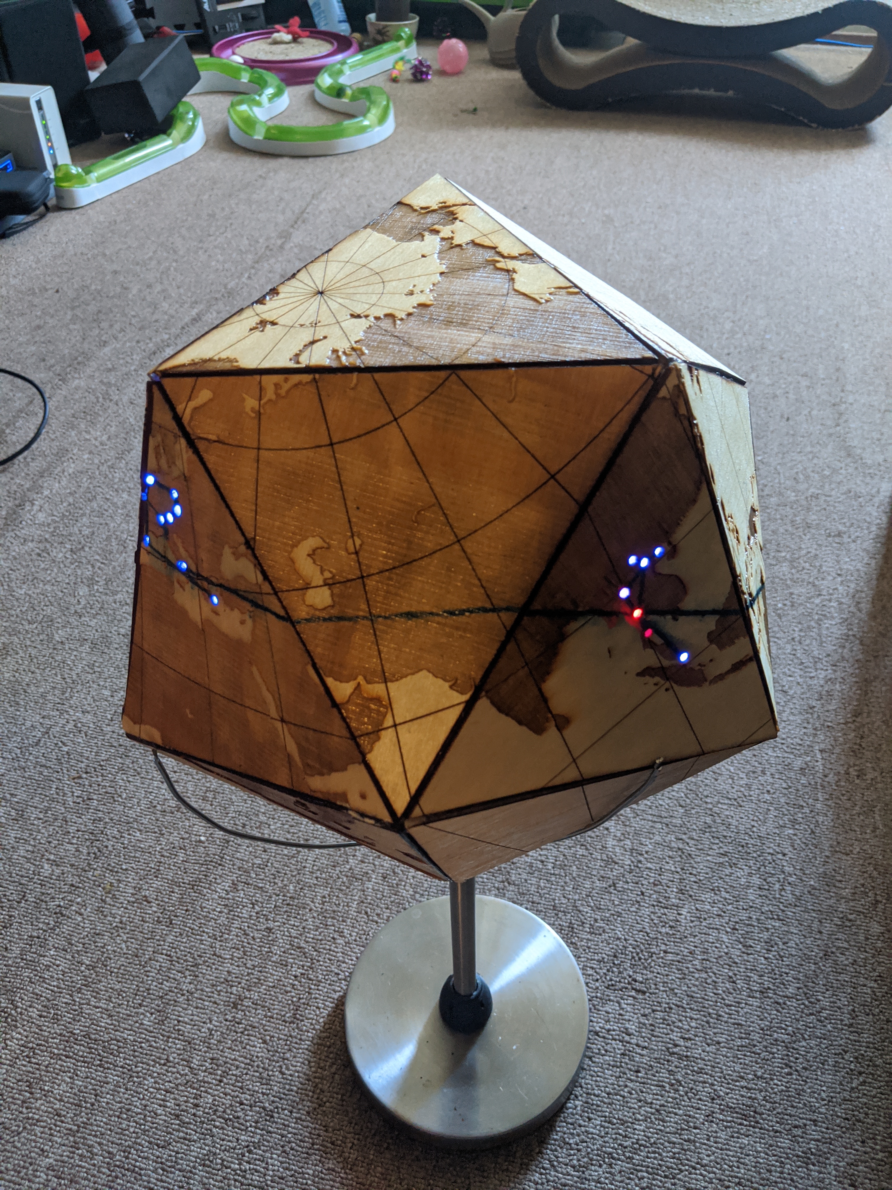
I added circles to indicate where the cities were, and in retrospect I probably should have indicated the travel path as well.
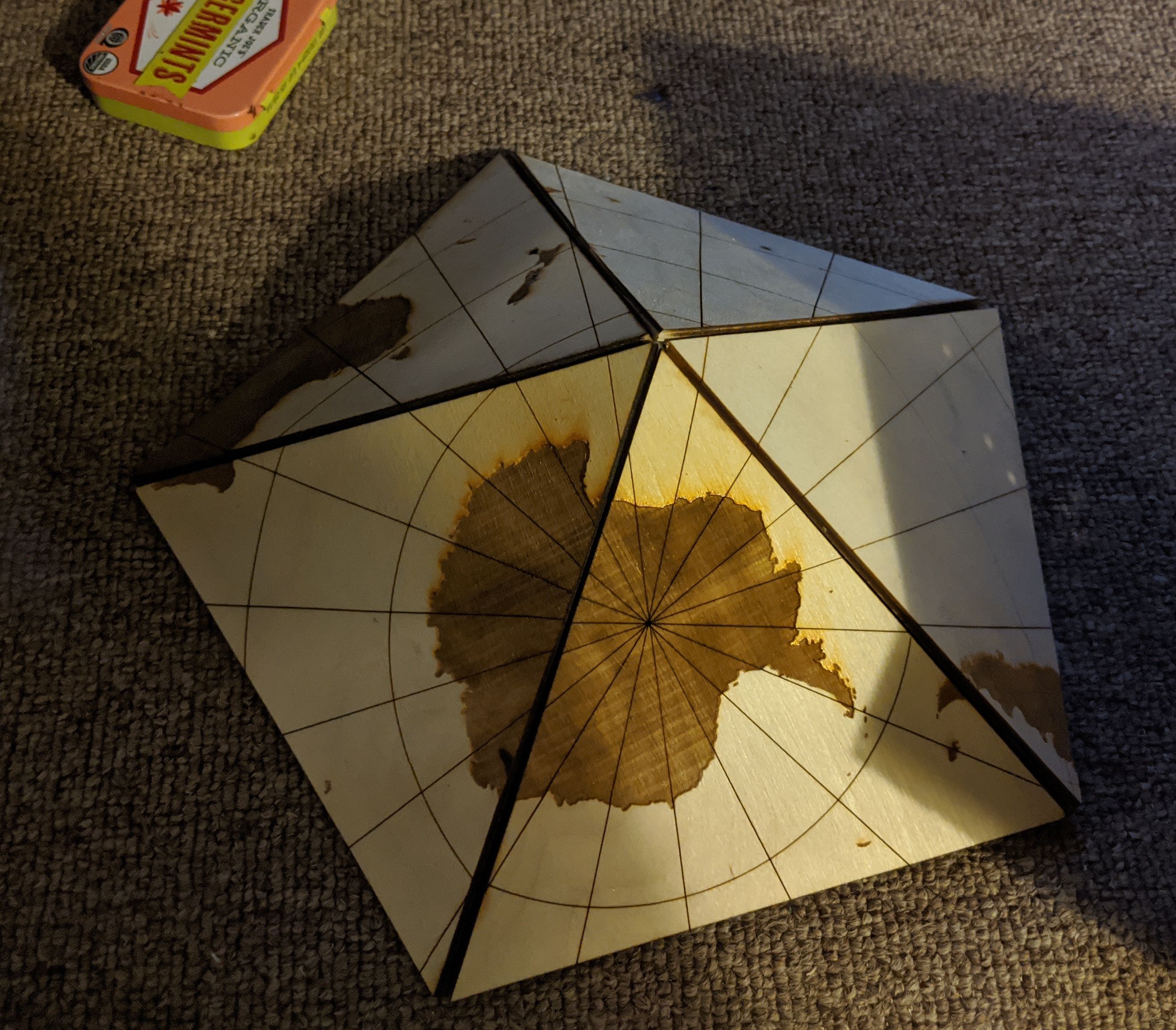
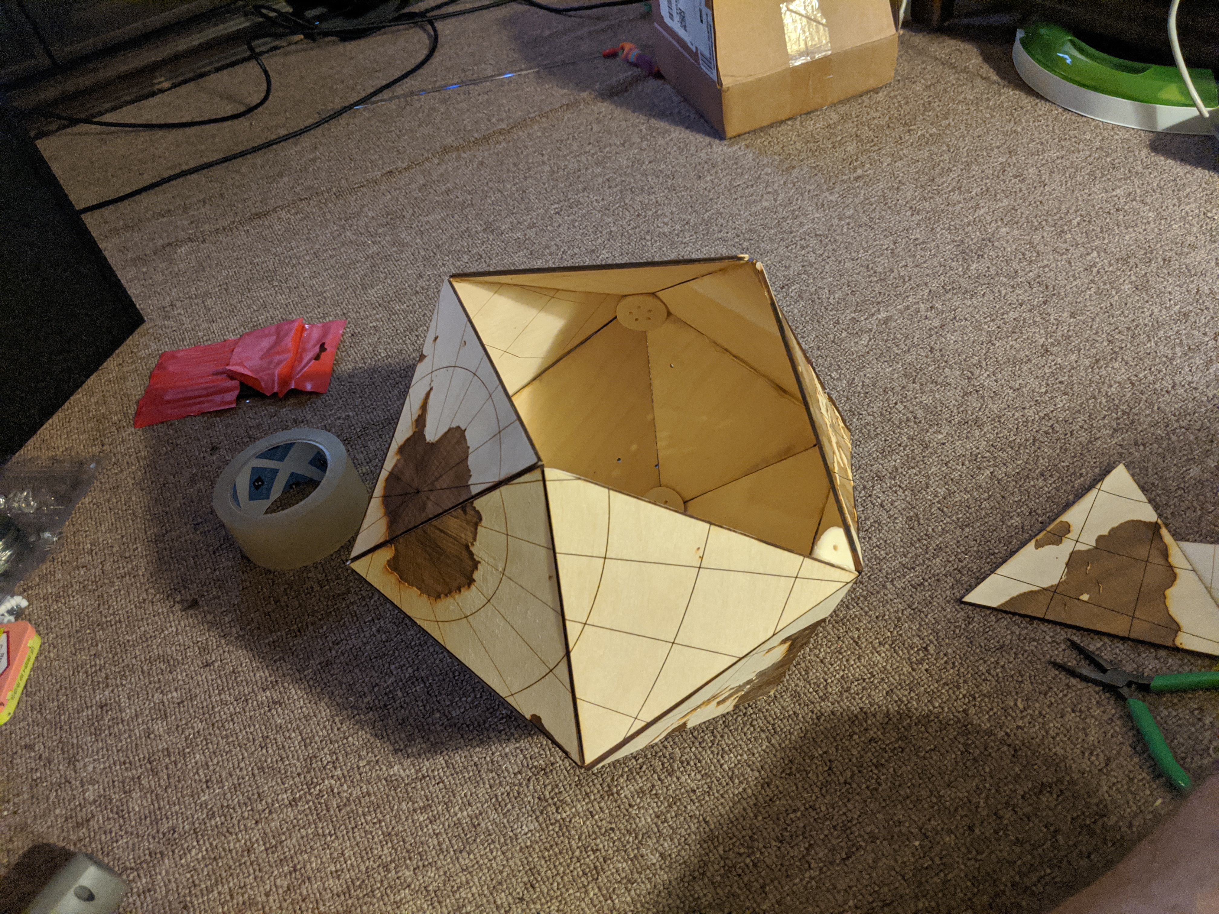
Here it is printed out:
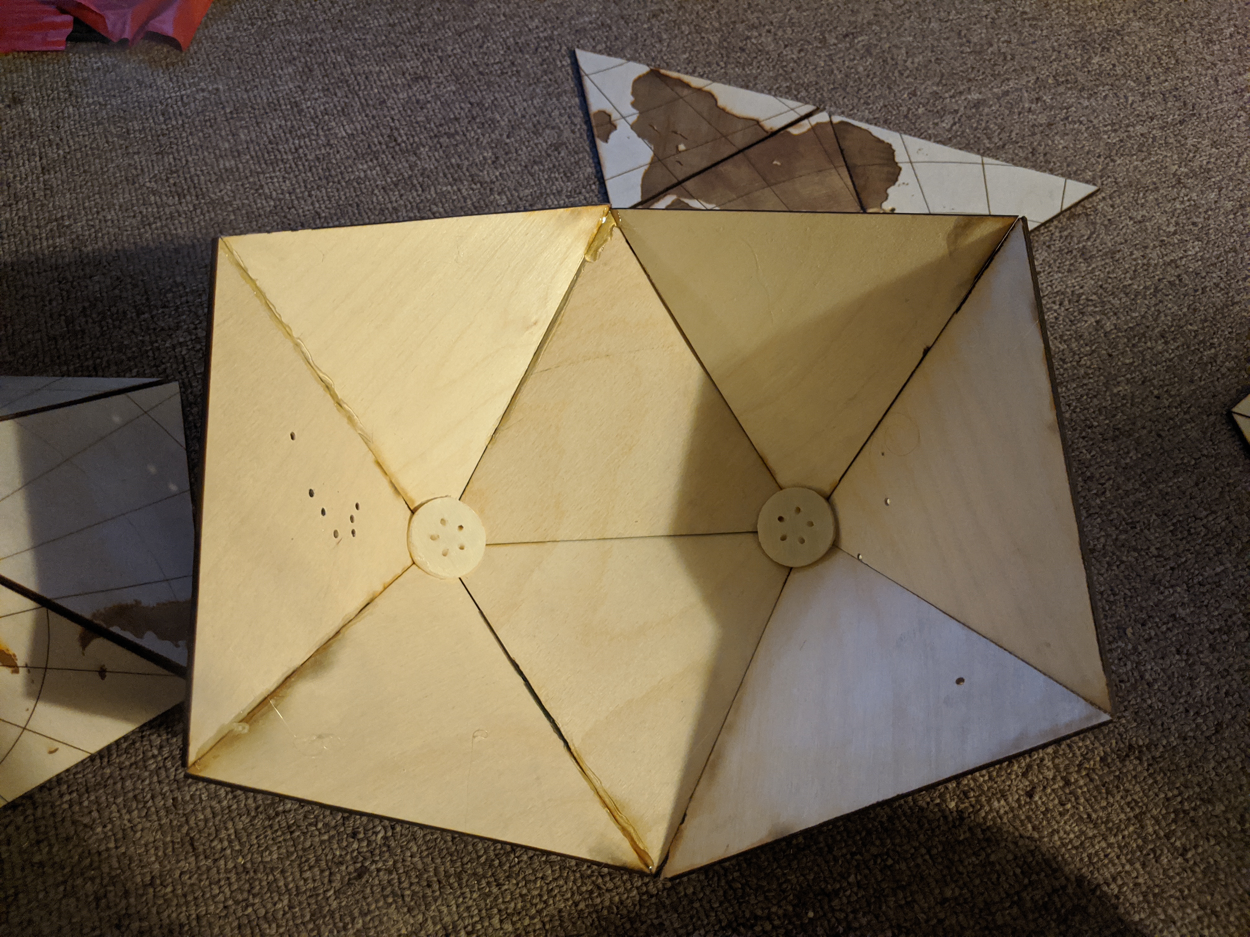
Rather than go with the screws used by the reference projects, I decided to hot glue it together. It was pretty finicky to put together and is almost certainly less sturdy. However, it’s nice to have the entire surface clear and seems fairly robust.
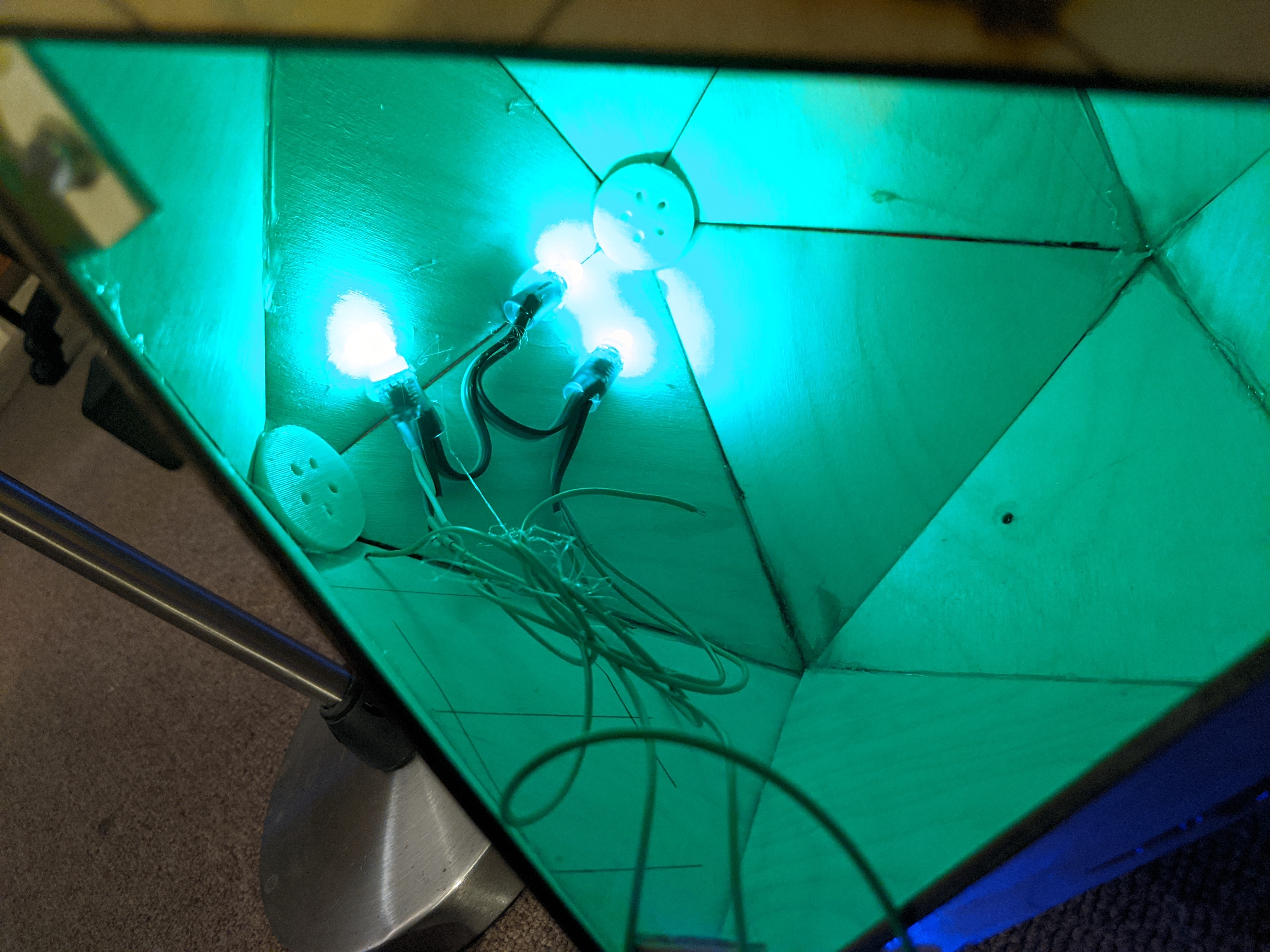
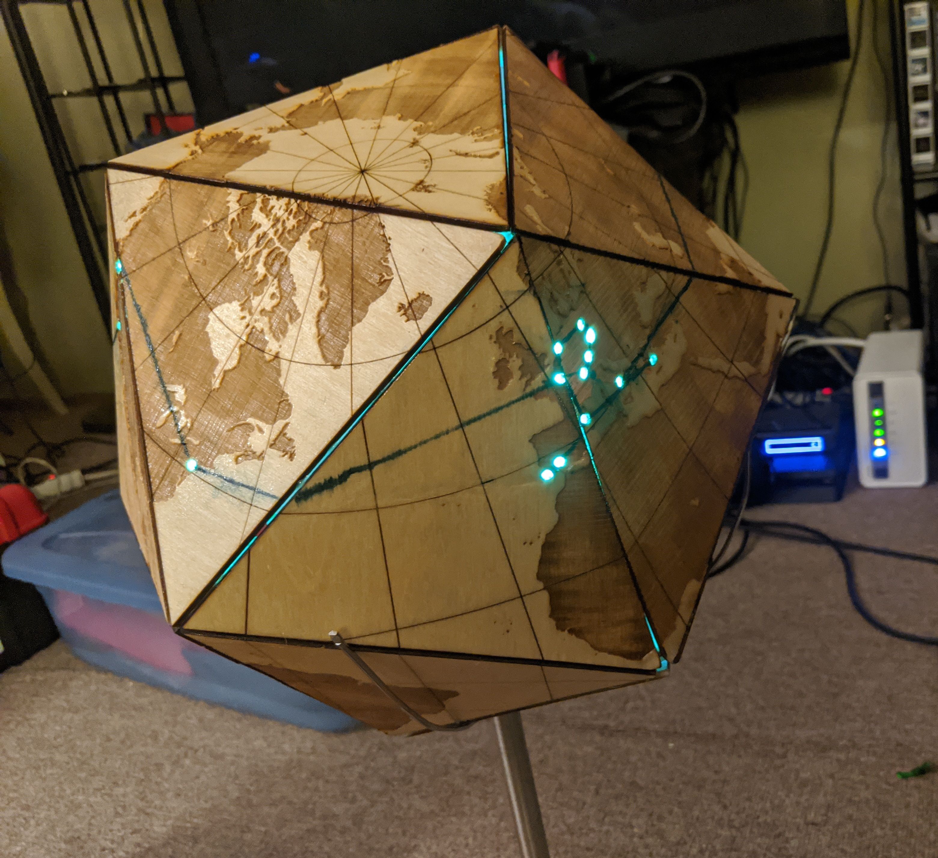
It took me a while to decide what to do in addition to the wood build. Unsurprisingly, I wanted to put LEDs in it. I wanted them to be interactive somehow, and eventually I came up with the idea of making it interact with a Google Maps photo gallery. The idea is to cut holes for the cities we visited and light up an LED under the hole when showing the corresponding pictures. We drew lines on the globe to connect the cities.
To make the innards accessible, I initially tried to build a hinge:
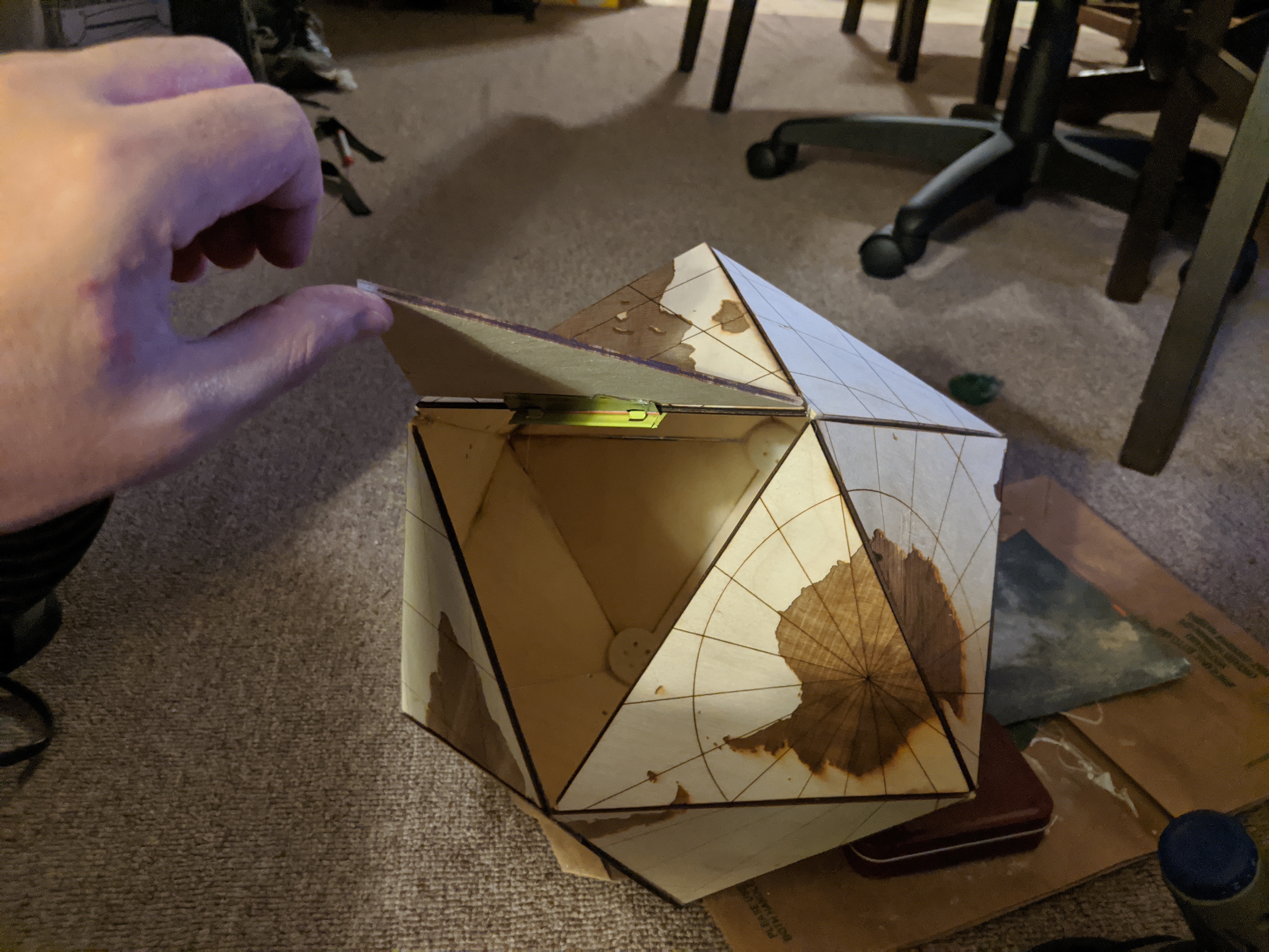
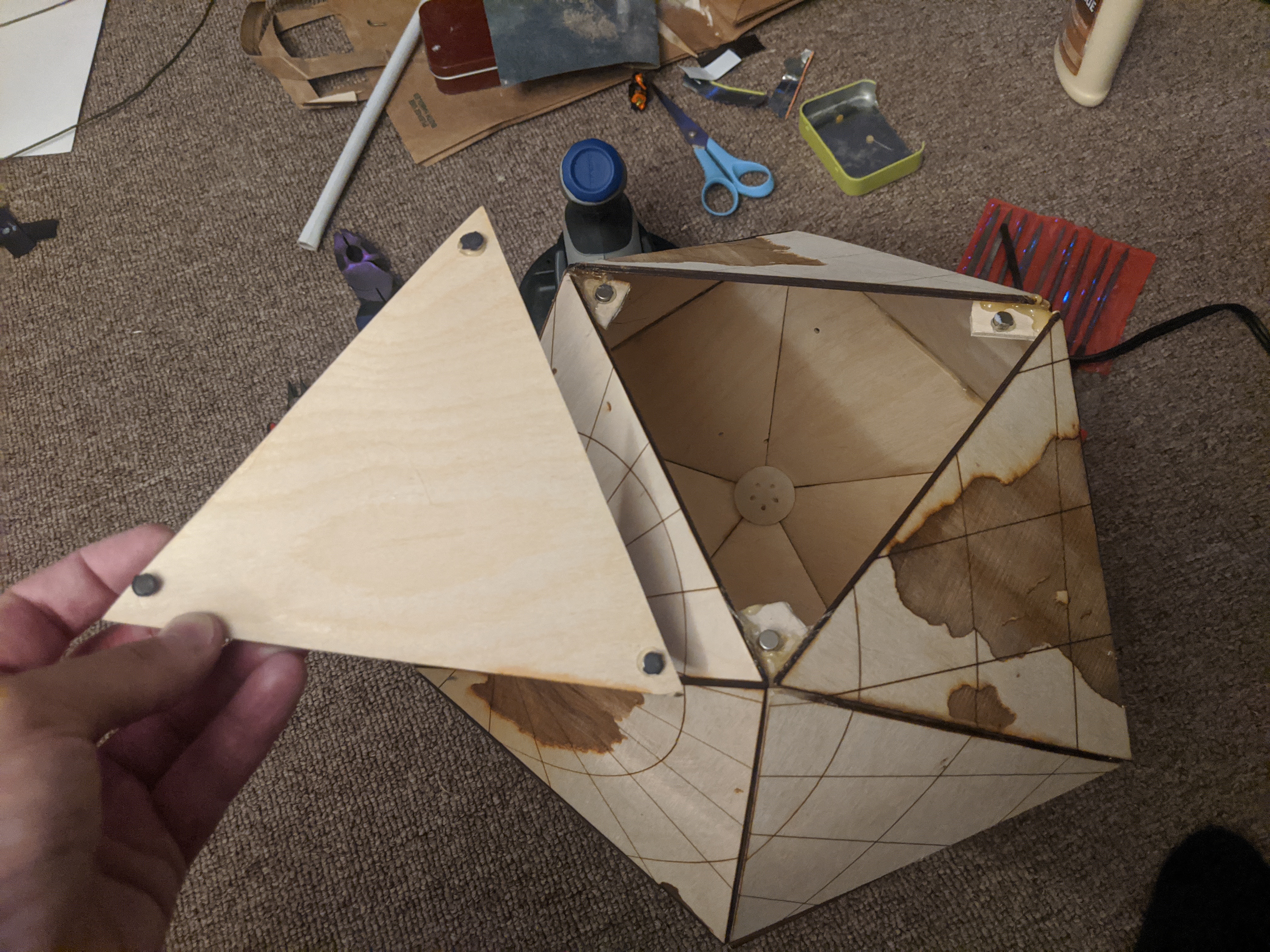
which worked OK. I wanted to to look nicer though so I ended up going with adding magnets to the corners:
Electronics Build
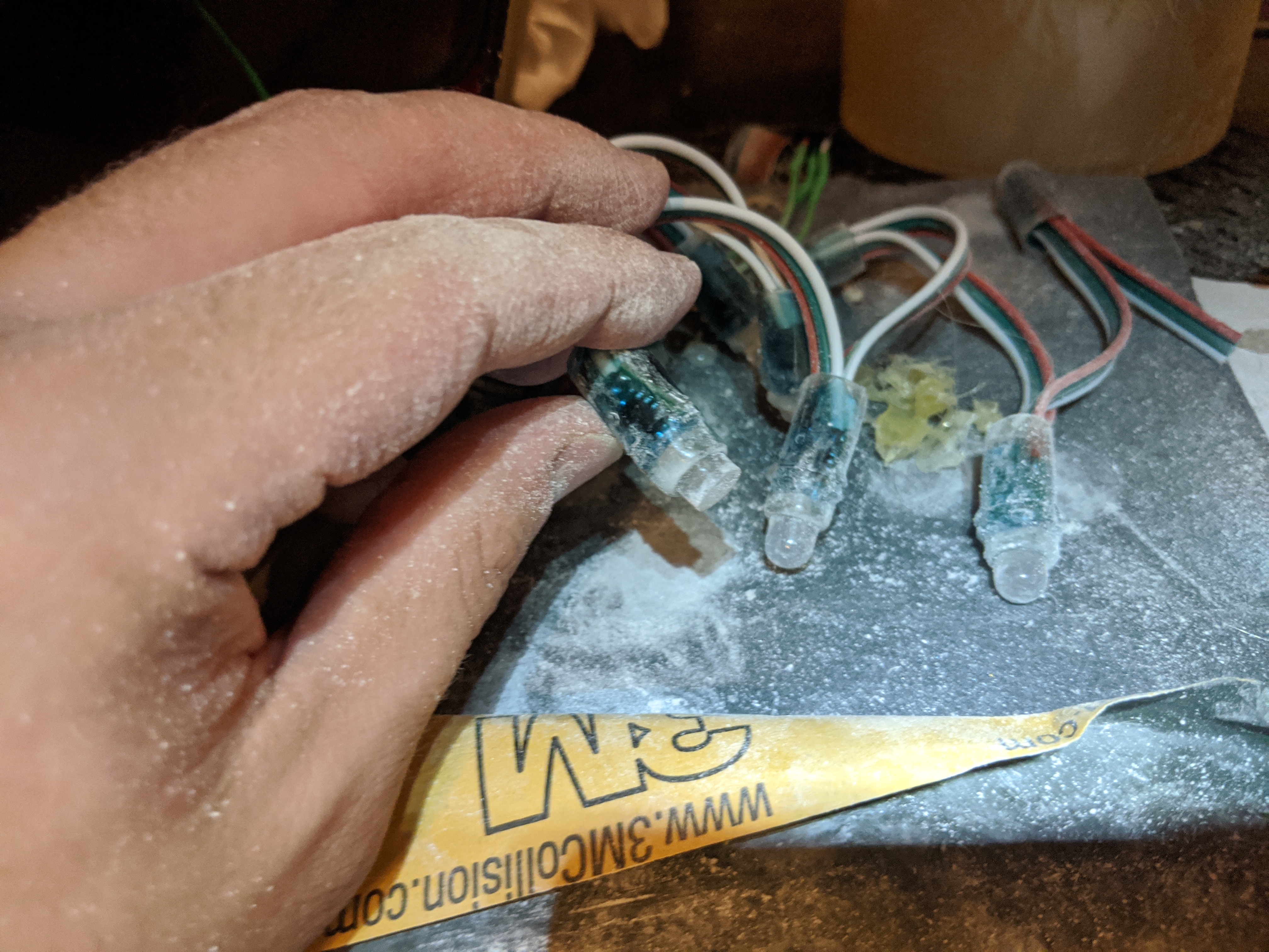
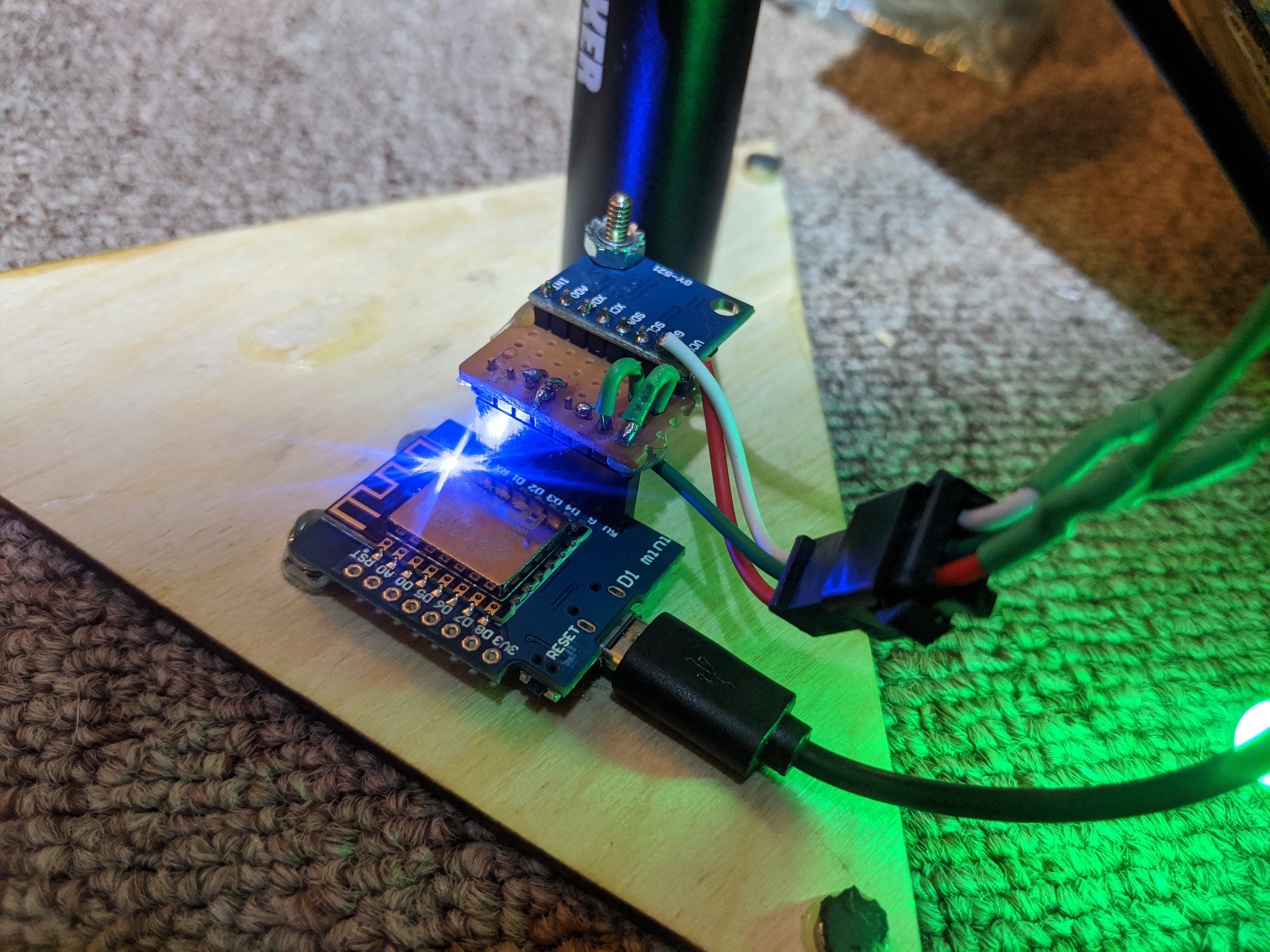
For the electronics I stayed in my comfort zone and went with WS2812B LEDs and a NodeMCU like in the (Wreath Pixel Display and (Fire Emblem Lights projects. Trying to save money, a cheaper ESP-8266 board, the D1 Mini. This worked great. I also went with the cheapest WS2812B string I could find. It turned out these were not the LEDs with the built in controller I was used to, but were actually pretty bulky lights.
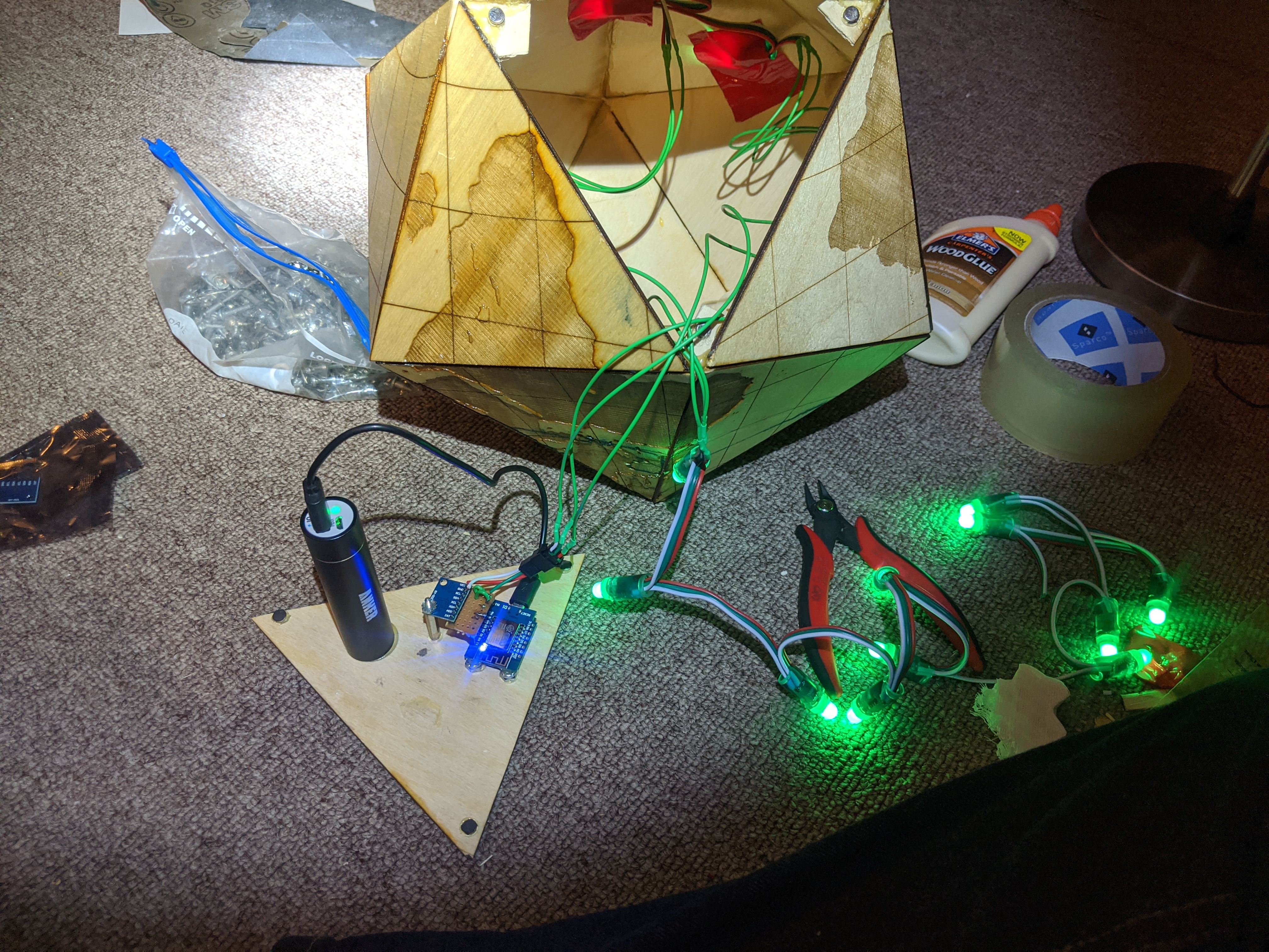
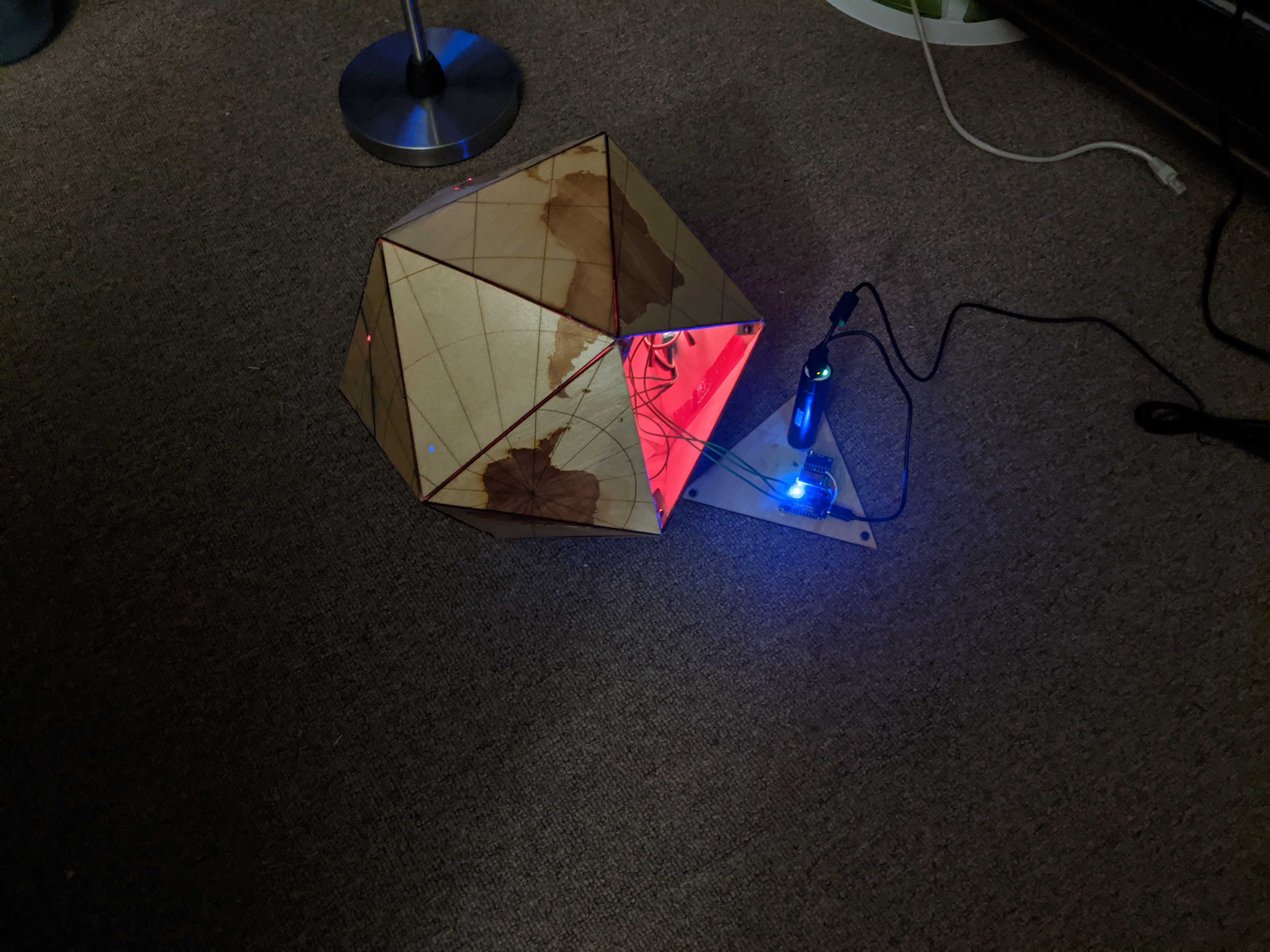
As you can see above, the controller is plugged into a USB power brick. This allows the project to be run wirelessly.
It was a struggle to glue the LEDs in place. For one, I should have done it before assembling the globe. Also, the round shape of the LEDs made it very hard to efficiently glue them in place. I ended up cutting the tops off with a dremel to make them flat.
In addition to having a gallery that controlled the LEDs on the globe, I wanted the control to work in reverse as well. I went with a mpu-6050 IMU which is a 6 axis I2C IMU. It even has some build in processing to handle some of the lower level sensor integration. I wired it into the nodeMCU, and tried to get the whole thing mounted sturdily.
Stand Build
Originally, I had grand plans of making a multi-axis rotating base to mount the globe in. I could have even looked into wireless, or magnetic contact charging for the USB power pack. After playing around a bit with the materials I had on hand, I decided to take a much simpler approach. I ended up pulling apart a paper towel holder to make a stand with minimal effort.
It originally looked something like this:
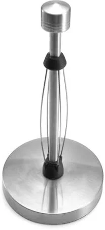
I took the top off and pulled the metal rods out of the base. I then bent them into a bit of a claw to hold the globe:
Software Build
The first thing I did was set up my photo gallery.
Inititially, I explored creating my own server in python to provide an interactive map along with a photo gallery. The library https://scitools.org.uk/cartopy/docs/latest/ seemed like it would be suitable, but I decided that I should try to take advantage of a less home grown solution.
I decided to use Google My Maps. This service lets you put photos, markers, and drawings on a Google Map canvas. It’s convenient since it lets you directly import from Google Photos and can directly use the location meta data embedded in the pictures. While this was really easy to get started with I ended up frustrated with its limitations:
- You need to have your photos in a private album. For whatever reason shared albums don’t show up.
- If you try to add a large set of photos it seems to randomly drop a large percent of them.
- It seemed to be unable to add photos directly uploaded from my PC, or from Google Drive.
- You can’t directly access a My Map from the Google Maps Javascript API. You need to do a bit of a hack with a shared KML export link: https://stackoverflow.com/questions/36533307/render-a-my-maps-using-google-maps-javascript-api
Once I got the map to load in the Javascript API I still had to do a bit of fighting to get it to do what I wanted. The Google Maps API is really not tuned to allow dynamic animations or responding to real time data. Here are some of the issues I hit:
- Even though I could display all the pictures from the exported My Map KML, the API doesn’t let you iterate through them. I ended up having to parse the KML and add the features in my Javascript code: https://stackoverflow.com/questions/3885123/access-kml-markers-in-google-maps
- There isn’t a built in way to smoothly zoom and scale between distant locations, so I needed to write my own animation: https://stackoverflow.com/questions/3817812/google-maps-v3-can-i-ensure-smooth-panning-every-time
Once I had the basics of the map working the next step was to start integrating everything together as a user mod to WLED. WLED added a new user modification interface, which made this even easier than expected. Strange that this open source project was so much friendlier then the Google development tools.
First I integrated in the IMU. I struggled quite a bit finding a PlatformIO library that worked correctly. This sort of integration really stretches the abstractions that the Arduino framework makes. I ended up needing to add a macro to an interrupt handler, and realize that the library was being silently rejected by a compatibility check. Eventually, I figured it out, and created a pull request back to WLED in case anyone else wants to use this sensor: https://github.com/Aircoookie/WLED/pull/1007
The next thing I figured out was how to interpret the IMU data in order to control the map. The MPU-6050 reports its orientation directly through some sort of sensor fusion. After a bit of experimenting I found that it wasn’t super accurate especially when it was rotating around one of the sensor’s axis. I also initially tried to calculate the expected angle rotations that would occur in order to have each of the 20 sides face up. Once I gave up on these I ended up with a very simple, robust solution.
With the script collect_face_gravity.py I would collect a series of measurements of the gravity vector as I sat the globe with one of the sides of interest up while rotating it. This would give me the gravity measurements that could correspond with that side being up. Next, I processed these measurements to find their centers, and plot them to make sure they didn’t overlap. Since they were quite distinct, this would work reliably. Here’s a plot of the 7 sides of interest.
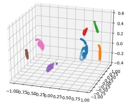
To find which side was up, I would compare the sensor measurement to these computed centers. I then just use the gyro measurement to detect if the globe was being rotated with a simple empirical threshold.
Normally, the web interface for WLED projects is compiled onto the microcontroller. Since Google maps needs an internet connection anyway, I ended up putting 99% of the code for controlling the project in a javascript file that could be imported from a remote source. This way I didn’t have to keep reprogramming the microcontroller to update the web client. The code for the web client is: https://github.com/axlan/WLED/blob/globe-deploy/globe_ctrl/site/map_ctrl.js
The main modification I did in the WLED software was to make it so the sequence of the effects would follow the route we took instead of just lighting up the LEDs in their order on the strand. Initially, I thought I would need to hack this in myself, but as I was modifying the code, I found the feature already existed! I enabled the custom mapping table: https://github.com/axlan/WLED/blob/globe-deploy/wled00/FX_fcn.cpp#L35. It’s a little weird since we didn’t solve the travelling salesman problem, and we back track. This means that the length of lights in the sequence is 32 even though there are only 24 LEDs. Fortunately, WLED handled this OK if I configured it to think there were 32 LEDs.
The branch with my entire WLED project is in: https://github.com/axlan/WLED/tree/globe-deploy
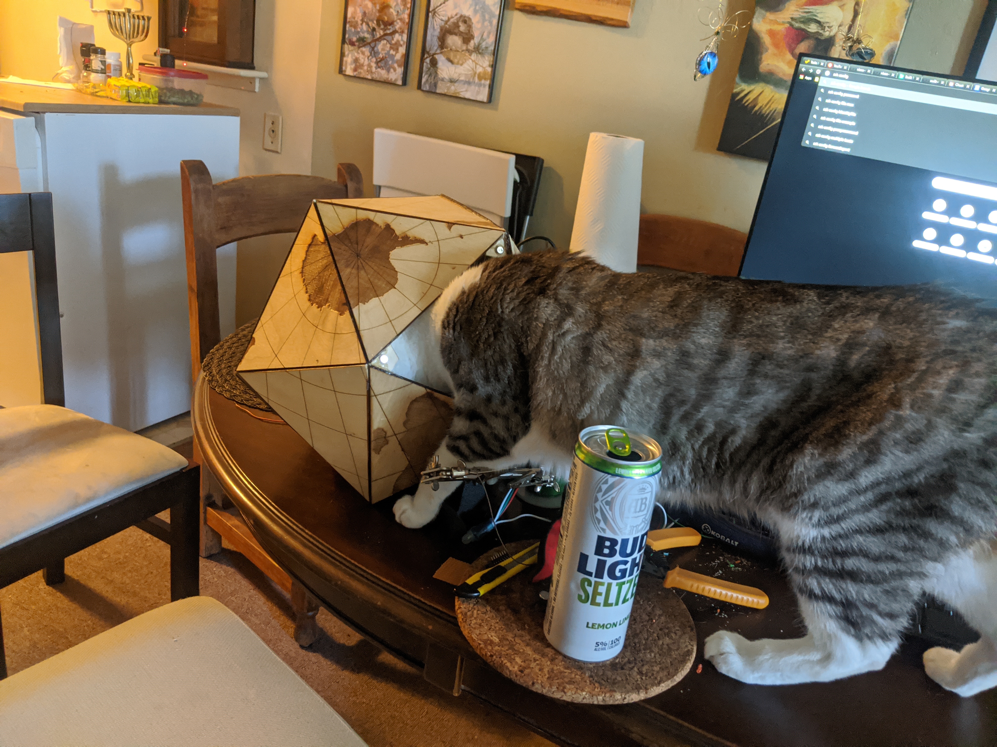
Bonus Cat