
Custom PCB Magic Card Game Life Tracker
I had my first circuit board printed. I made an extremely over engineered life total counter.
It’s mostly based around Magic the Gathering, but could be used for a variety of games. To make it interesting, I made it track multiple totals (tokens, counters, commander damage, etc.) and to be able to quickly add and subtract large numbers.
The interface I came up with was:
- Show a total in a seven segment display
- Show which total is selected in an OLED display
- There are ten totals, each with an icon to identify them
- A list of numbers to identify the totals on top, with the current total highlighted
- Have an increment and decrement button
- Have and up, down left and right button
- Up and down will change how much the increment and decrement buttons add. This can be 1, 10, 100, or 1000. The current selected value is shown by lighting up the decimal place led for the corresponding digit.
- Left and right switches which total is being displayed
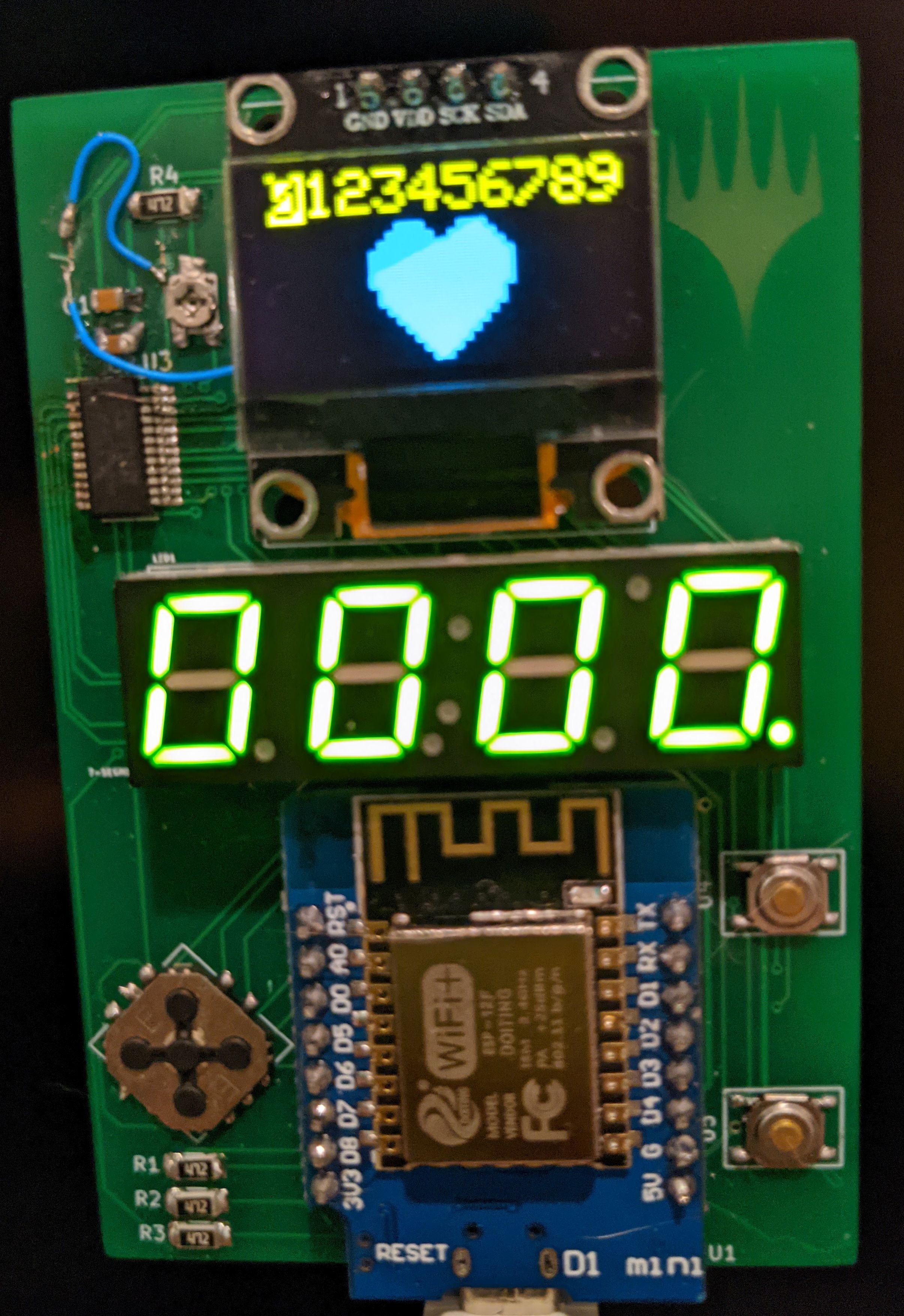
Here’s my initial prototype in action:
All the designs and code can be found at https://github.com/axlan/mtg-life-tracker
See this update at the end for my second revision with improved ergonomics and a lot more software development.
Coming Up With a PCB Project Idea
I’ve been looking for an excuse to do a PCB design project. While I’ve designed a few boards for school and work, I’ve never had a PCB manufactured for a personal project. This is mostly because I’m impatient and don’t want to wait weeks to iterate on a design. Also, it can be intimidating. There are a lot of things you need to get right for a non-trivial board. Since I haven’t used the tools much there’s also a pretty steep learning curve. Still, prices have come way down since the last time I looked into it, and I could get a board design printed and shipped for under $10.
I wanted to choose a project that wasn’t too big, but would actually benefit from making a PCB. I was thinking of making a general development board with a cute design. I’ve been impressed with PCB art and use Defcon badges as a benchmark https://defcon.org/html/links/dc-badge.html.
I recently bemoaned that the free apps for tracking life total in Magic the Gathering are pretty bad. Besides the apps themselves being subpar, using your phone for this application is not ideal, between needing to make sure the screen stays on and is readable, while draining battery. At the minimum a life tracker just needs to display a value and be able to increment up and down. I realized this could be a good opportunity to design a custom board.
Prior Art
After a bit of googling I found that there was a commercial option available. In addition there were a few neat projects that people had done:
- This is pretty, but I was looking for something more practical.
- This one took the PCB art element to the extreme.
- I found this one the closest to what I was thinking of.
The main nice to have features would be:
- Being able to to increment the counter up and down by different values (+1, +10, -20, etc.).
- Being able to track multiple different counters (life, poison, entergy, tokens, commander damage, etc.).
- Being able to do dice rolls
High Level Design
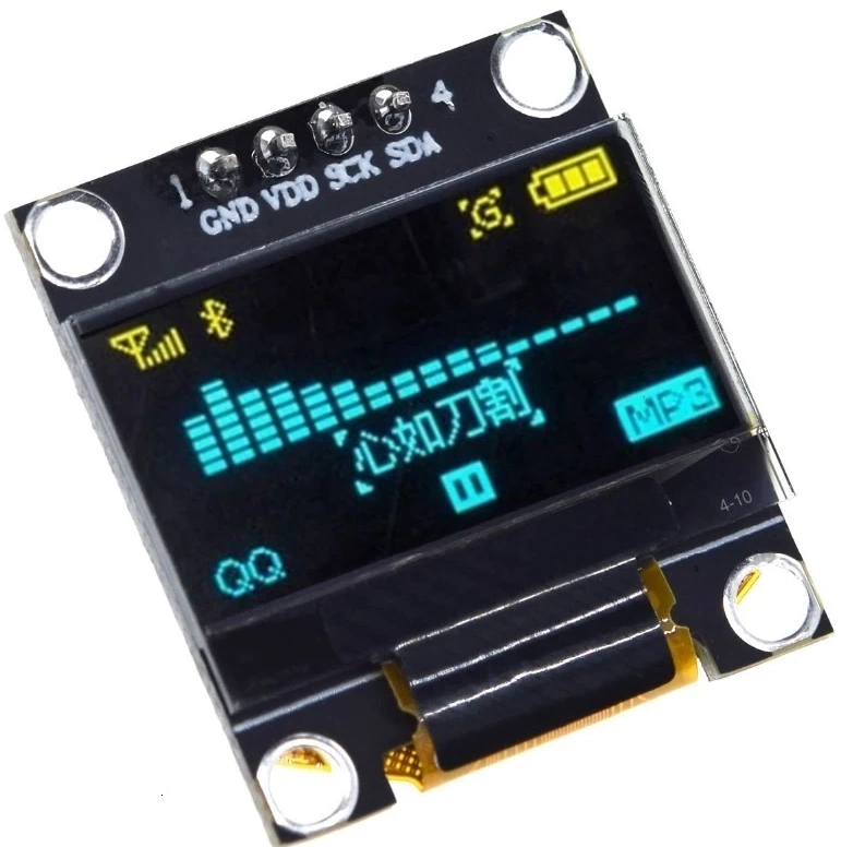
I first had to decide the big picture I was going for. I decided it would be neat, if it was the same size as a card. In addition I wanted to use a random OLED display I had lying around. Eventually I settled on using seven segment displays as the main indicator, and the OLED display as a secondary display.
I decided to go with a ESP8266 dev board for the processor, since I thought it might be neat to make it configurable through a web interface, or be able to have some sort of communication between paired trackers.
Picking the Parts
The next step was to decide on the bill of materials (BOM). I worked on this on and off over the course of a couple weeks. I was reminded how the hard part is often just figuring out the what chips exist since there’s often some very specific part that can fit your use case extremely well.
I started off with the previously mentioned OLED display. I had gotten it as an impulse buy off AliExpress. I had thought this would be a fairly standard part, but it turns out there are tons of these dev boards that are very close to interchangeable, but with slightly different sizing and pin ordering.
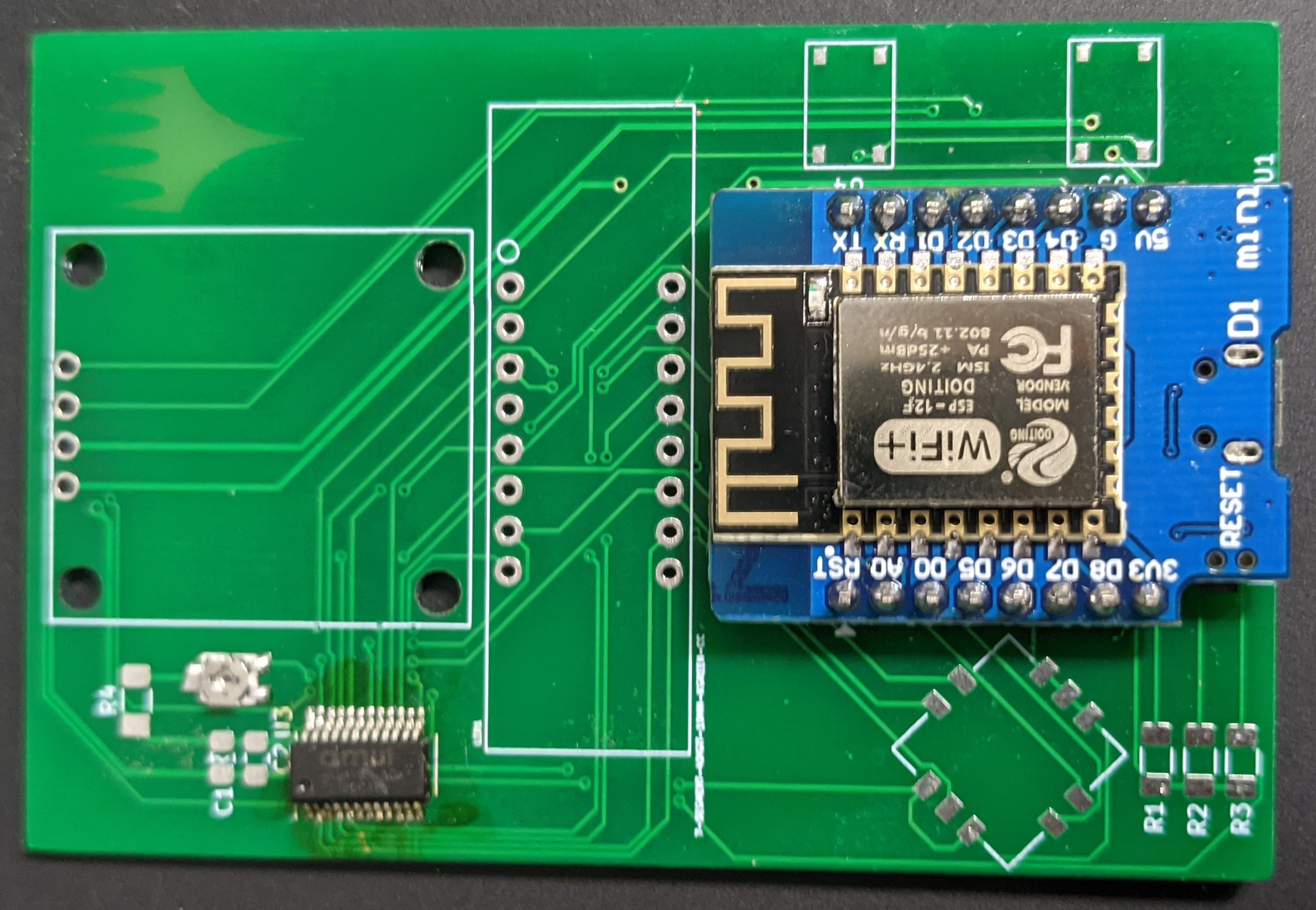
I also had some D1 mini ESP8266 dev boards lying around. I decided to go with these since they’re relatively small, and handled the USB and power regulation. I considered going with a minimal ESP module, but since this is my first board, I figured I should start off easy. In addition I had a different display that I could mount on top of the D1 dev board if I wanted for a second build.
For the rest of the parts, I browsed Adafruit and Sparkfun for ideas, but pretty much relied on Digikey for their extensive part search.
I wanted to copy something like this Adafruit dev board for the seven segment display. Reading the details of the IC they use, I was interested to learn it could handle reading key presses as well which would be great for my use case. Unfortunately, I couldn’t find the chip they used for sale at a reasonable price.
These chips are able to control dozens of outputs with only a few outputs. The can do this with techniques like Charlieplexing, and by only being able to control sets of LEDs at a time, and switching between the sets faster than the eye can see.
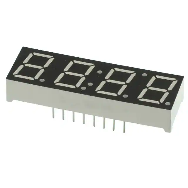
Digikey let me find some candidate substitutes. Early on I found the cheapest way to get 3 or more segments was to get a clock display. Not only is this pretty cheap, but it also reduces the number of pins that would need to be wired up.
I was kind of shocked at how expensive all the display drivers were though. They seemed to be selling at twice their normal price. Presumably this was from the chip shortage. I guess I didn’t pick the best time to be doing this project. Eventually, I chose the MAX6958 as my candidate part. It was a reasonable price, and seemed to cover my use case. Eventually, I realized that only it’s variant the MAX6959 did the additional key press handling which made me a little less excited by the price. I started doing the board design, and realized another problem. These chips assume that the segments can be separately accessed. This lets them share some of the control pins. This would mean I’d need to switch to a more expensive display.
I did an entire schematic with this part:
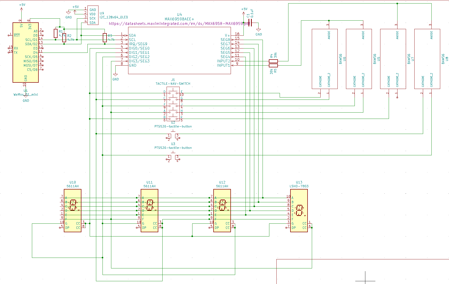
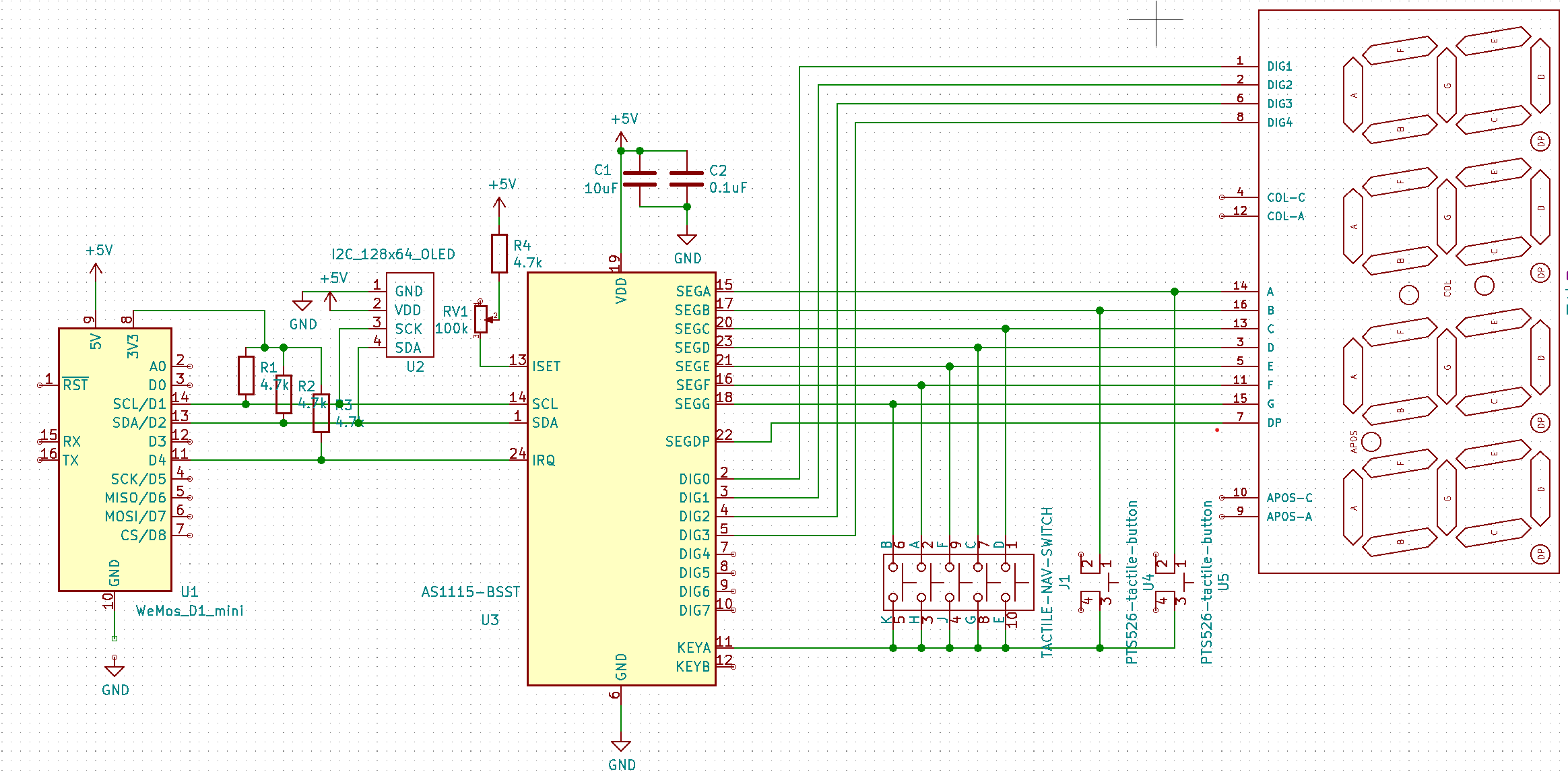
Shortly after I finished, I found a cheaper part that better fit my design, the AS1115 and had to somewhat start over.
The rest of the parts were passive components like resistors and buttons which I mainly selected for low cost. The only interesting part was the joystick navigation button.
Designing the PCB
In the past I’ve used both extremely bare bones open source design tools (gEDA back in college), and the fairly expensive Altium tool at work. PCB design has never really been my primary role, so while I can figure out my way around these tools, I’m generally just scratching the surface. They’re like any complex design program where you’re only really productive once you understand the quirks, and memorize a bunch of hotkeys. I decided to go with what appears to currently be the most popular open source tool KiCAD.
PCB Design is usually separated into two pieces; the schematic design, and the PCB layout. I’ve done schematics occasionally for projects since they are just drawings to show the interconnections between parts. You can fudge things a bit since you’re not physically building it. The PCB layout on the other hand requires all the parts be accurately represented down to a fraction of a millimeter.
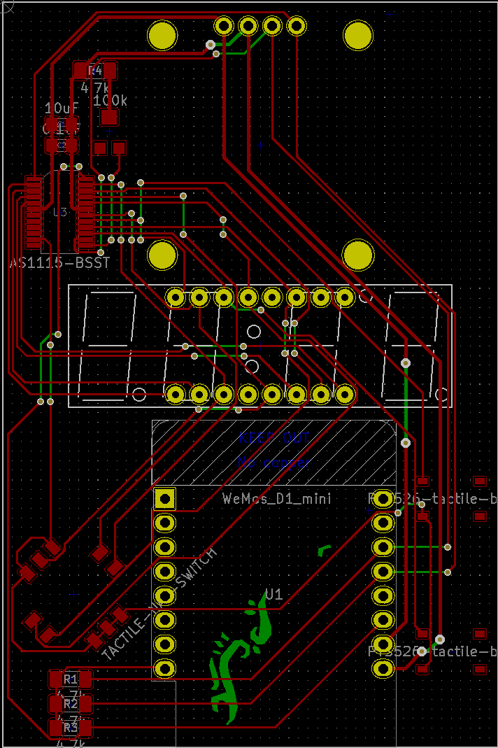
You also get to the “game” of PCB design, which is laying out the traces. The traces are “wires” of copper across the board used to route the signals. Since you’re working in a 2D plane, they can’t cross each other. You use copper plated holes through the board called vias to jump between layers to allow the traces to pass under each other. Some tools can do this somewhat automatically, but I decided not to pursue that approach and did it by hand.
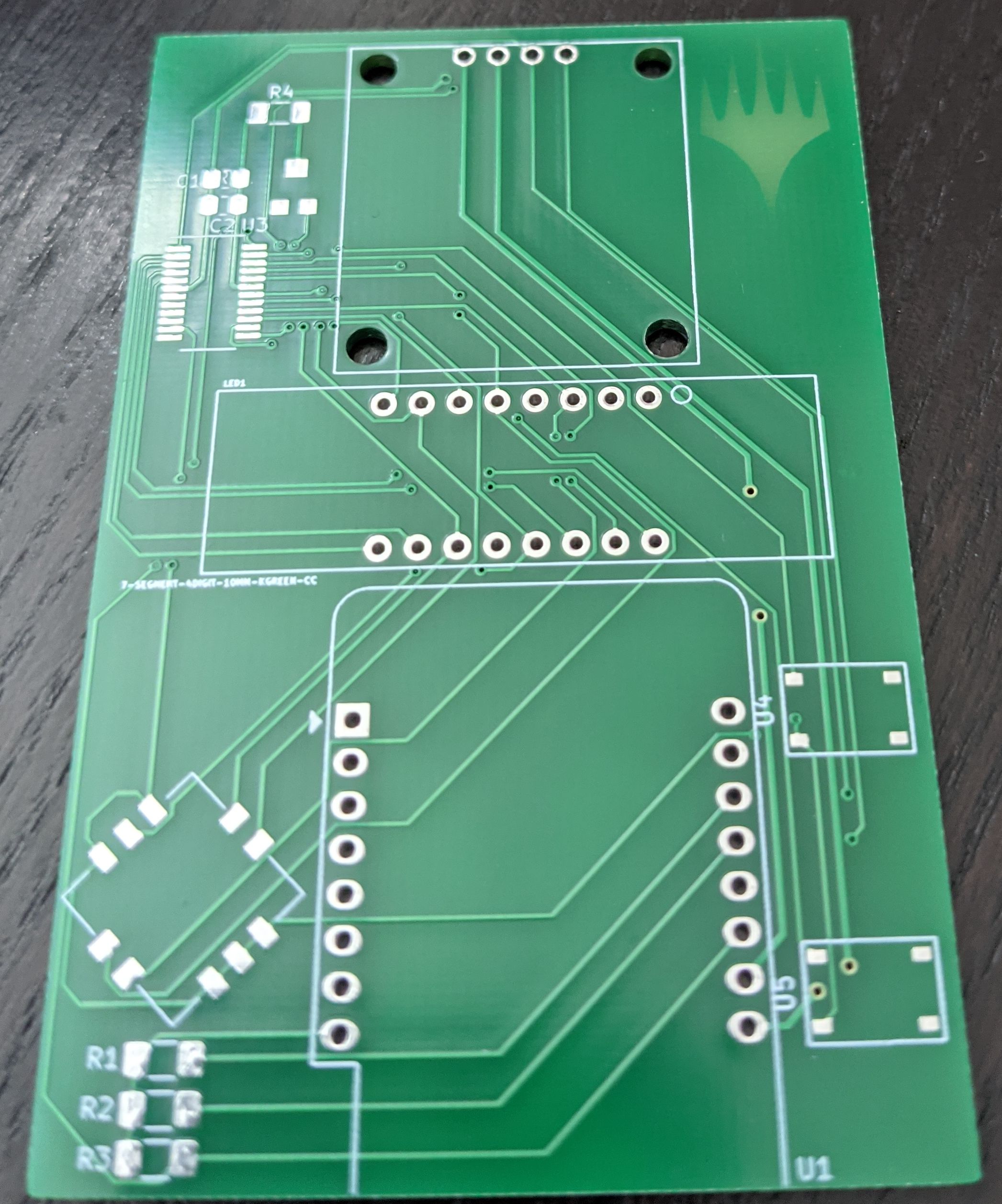
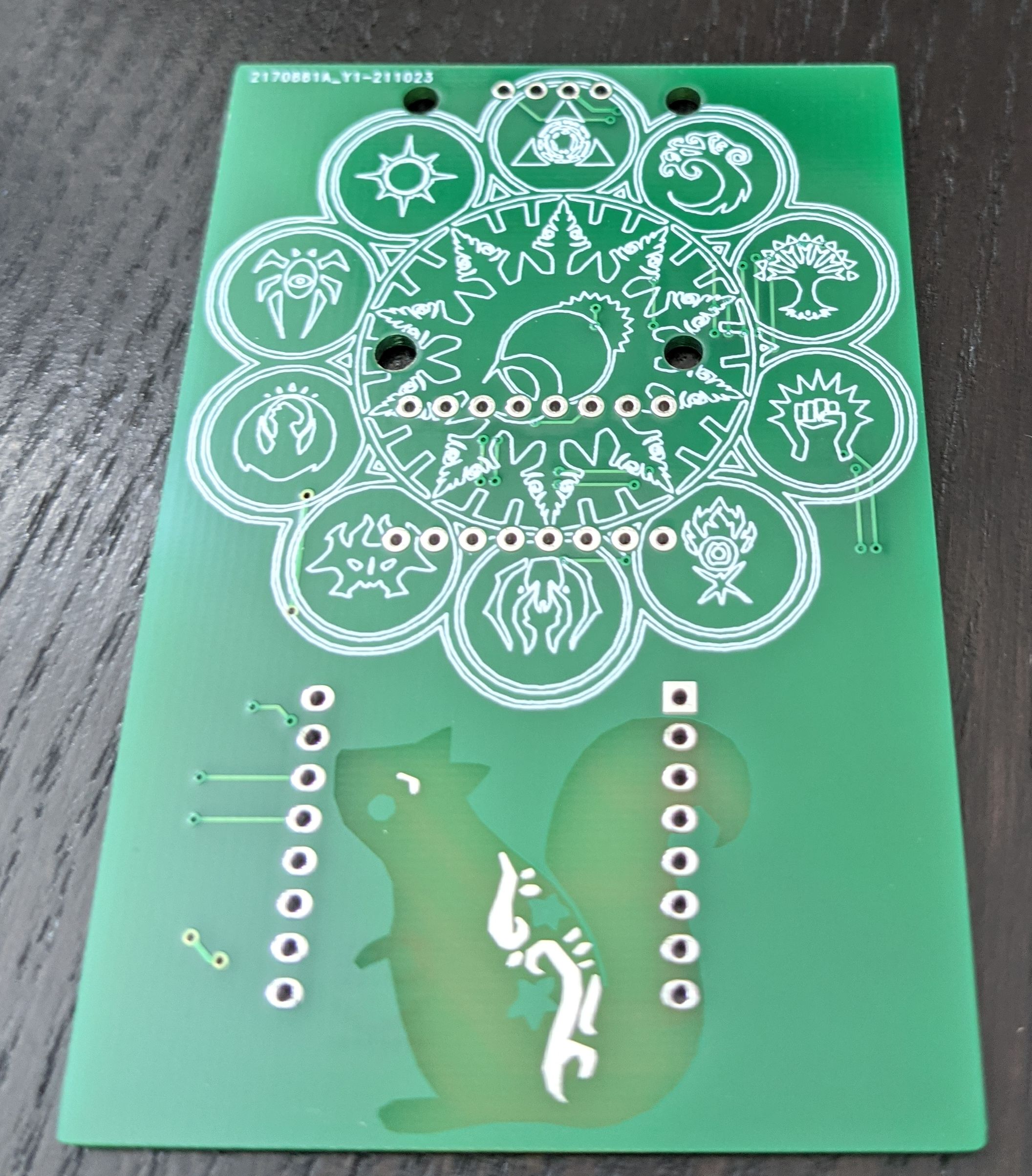
Adding PCB Art
One of the main goals of the project was to add some art to the design. Fortunately, there was a very easy to follow article that laid out the process for KiCAD in detail: https://blog.wokwi.com/a-practical-guide-to-designing-pcb-art/. I got to dust off Inkscape and do some more vector art.
While that guide walks through a couple different process, the best way to get an image on the board was to make a vector design in Inkscape and to use the tool: https://github.com/svg2mod/svg2mod to convert the SVG to a KiCad footprint. You name the layers in your design to match the PCB layers, run the file through the python script, and you get a footprint you can move around the board. The main trick is that since the layers represent production processes, there’s some gotchas in how they need to be stacked on each other. By stacking the layers you can get 4 or sort of 5 different colors:
- default - For regions that don’t have anything on any layer, they will be the color you choose for your board, traditionally green.
- mask - Confusingly, the mask layer is where mask will not be used. If you get rid of the mask and don’t add anything, you’ll get the actual color of the underlying board, a yellow brownish color.
- copper - With just copper, it will be hidden under the boards mask. This will be the board color but a little lighter.
- copper + mask - this will actually expose the copper.
- silk - This will be white or whatever the silkscreen color is. The silk will only show up on areas where you haven’t removed the mask.
Since I didn’t have any components on the back of the board, I adapted a couple designs:


Getting it Printed
After a brief look at the low cost PCB fab options, I went with JLCPCB. There’s a pretty straightforward guide for exporting the KiCAD files so they could be uploaded: https://support.jlcpcb.com/article/149-how-to-generate-gerber-and-drill-files-in-kicad . Once you’ve uploaded the files, they have a pretty decent preview tool that let’s you see what it will look like printed.
The board only cost a couple dollars to make, and I think it ended up costing $10 or so after shipping.
The board is manufactured after only a couple days, but the shipping took a couple weeks.
Assembly
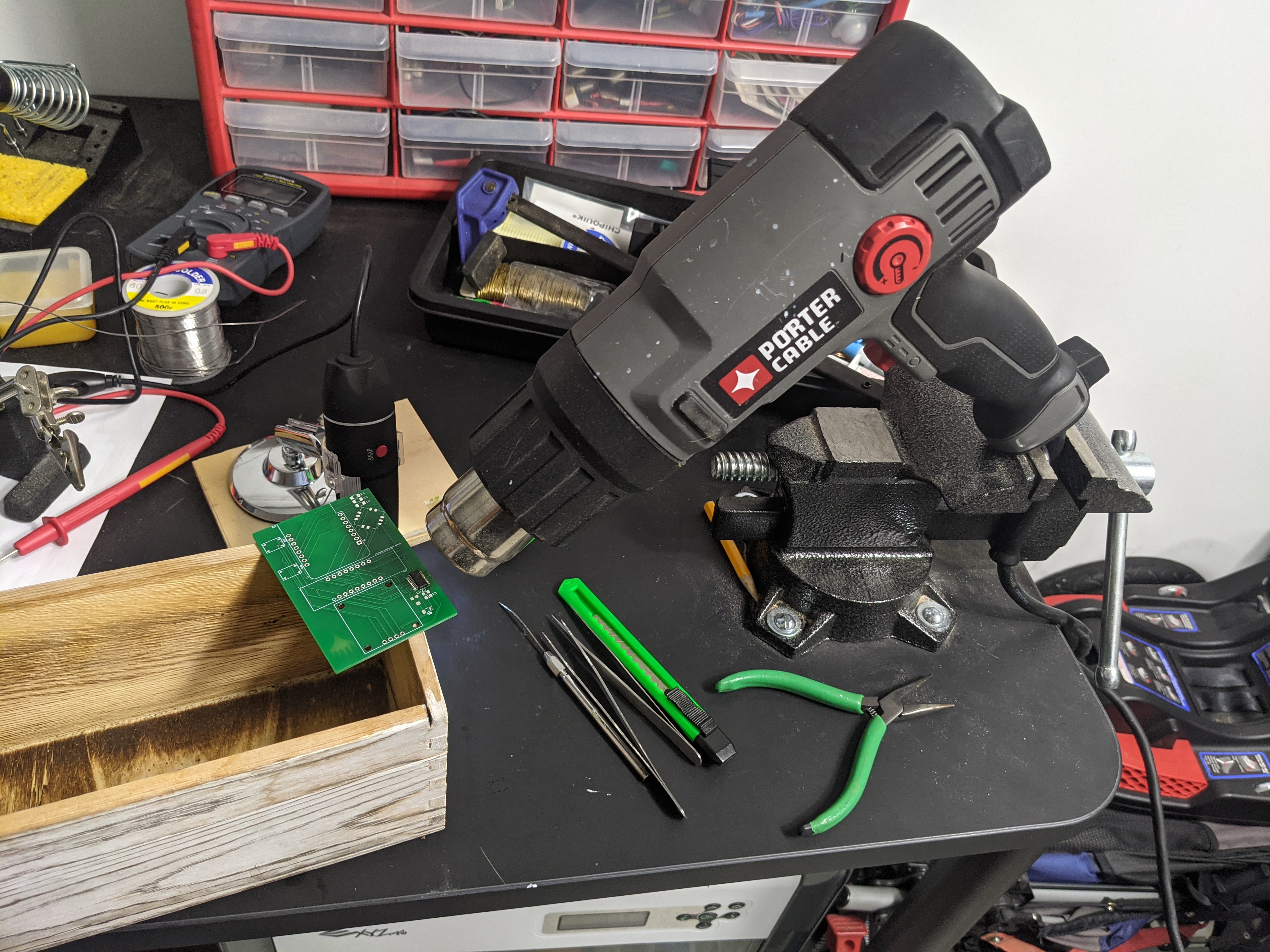
For the most part, the board is easy to put together. The one challenge was attaching the AS1115 since the pins were so small. I actually got a cheap digital microscope to try to aid in this process.


This helped a bit for inspecting the part, but didn’t help much for making the process easier. Getting the chip on and lined up was easy enough, but actually getting all the pins soldered was a frustrating process. I tended to bend the pins as I was trying to solder them, and had a lot of trouble fixing any pins I bridged. I ended rigging up soldering the pads, then using hot air to get the chip soldered. This worked great, but I tried touching it while it was still cooling, and accidentally shifted it slightly. Everything was still connected properly, so I just left it looking a bit ugly.
Testing / Mistakes
Once I had the AS1115 soldered on, I wanted to test it to make sure I hadn’t damaged it from all the heat. I soldered on the ESP8266 microcontroller and started testing.
The only additional component I needed to add was the pull up resistors needed for the I2C bus.
I wrote some test code and much to my dismay, I was not getting a response from the AS1115. Checking this out on the scope, I was not seeing the expected ACK so there was no sign of life from the chip.
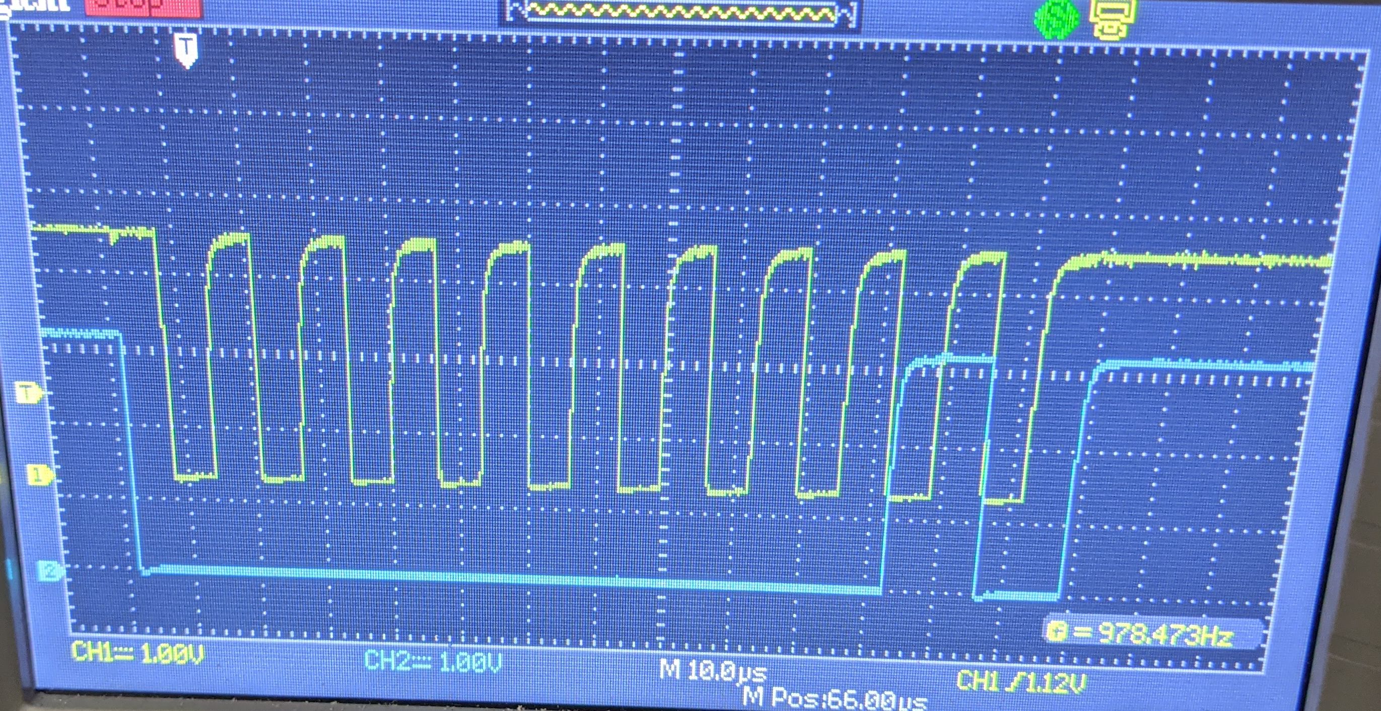
My initial thought was that this was due to a design decision I’d made that violated the chip’s specs. The board uses both 5V and 3.3V. I powered the AS1115 and OLED with 5V, and the D1 mini board does it’s own 3.3V conversion for the ESP8266. I used 5V for the two displays since the 3.3V converter on the D1 board has a fairly low current limit. I made the I2C between the chips 3.3V since generally I haven’t had issues with 5V chips receiving 3.3V I2C and didn’t want to add unneeded converters. I was able to mod the board to run everything at 3.3V, but this didn’t fix the issue.
After spending a lot of time examining the board, and the AS1115 datasheet, I took a more careful look at my schematic, and realized that the I2C clock and data lines were swapped for the AS1115. I had wired it up wrong when I swapped MAX6959 for the AS1115.
Fixing this was a bit rough, I did a quick and dirty rework by exposing and slicing the traces with an exacto knife:
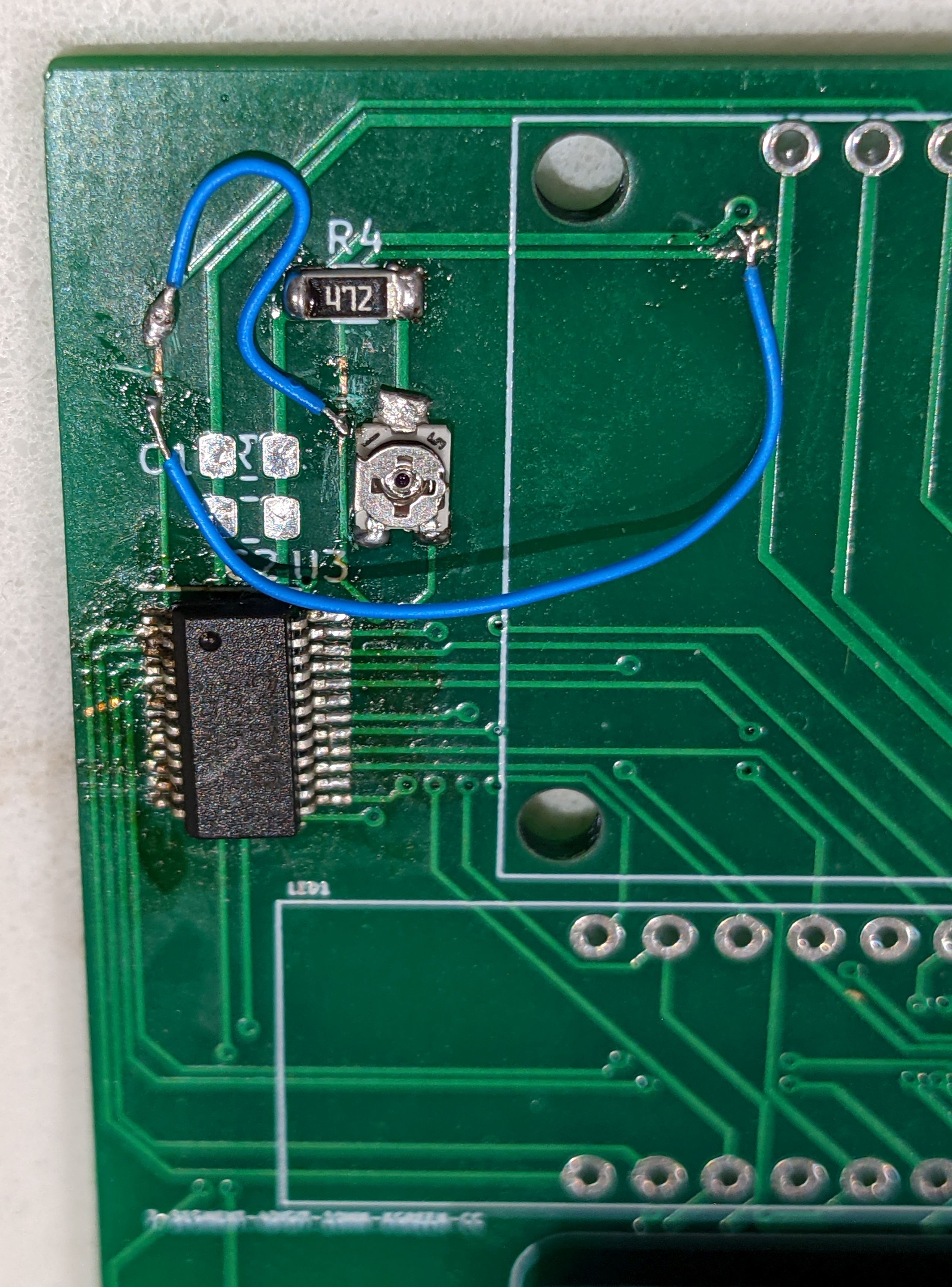
In retrospect, I probably should have done the jumping from the oled connector. With this done I wired up a button and confirmed that the chip was basically working.
When I went to test the interrupt, the ESP8266 would just crash. I realized I needed to add the IRAM_ATTR to the interrupt which I always forget when developing for this processor.
Much to my surprise, I had no further issues and pretty much everything just worked, both on the hardware and code side:
Really the only complaint was that that the buttons were a bit too small. I needed to use my fingernails to press them consistently.
Software Development
Once again I’m using PlatformIO for the firmware: https://github.com/axlan/mtg-life-tracker/tree/master/firmware
There was a fairly bare bones library for the AS1115. To make my life easier I ended up forking it to be able to arbitrarily set the decimal place. This was to support using the decimal place LED to show what digit the increment and decrement buttons would be changing.
The OLED library was much more mature. I did end up writing a simple Python script to convert black and white BMP images to C arrays that I could display https://github.com/axlan/mtg-life-tracker/tree/master/python. Here’s an example output, it’s neat that you can sort of see the image in the data.
1
2
3
4
5
6
7
8
9
10
11
12
13
14
15
16
17
18
19
20
21
22
23
24
25
26
27
28
29
30
31
32
33
34
35
36
37
38
39
40
41
42
43
44
45
46
47
48
49
50
51
constexpr uint16_t GOBLIN_WIDTH = 48;
constexpr uint16_t GOBLIN_HEIGHT = 48;
static const unsigned char PROGMEM goblin_bmp[] = {
  0b00000011,0b00000000,0b00000000,0b00000000,0b00000001,0b11100000,
  0b00000011,0b11100000,0b00000000,0b00000000,0b00000111,0b11100000,
  0b00000011,0b11100000,0b00000000,0b00000000,0b00000111,0b11100000,
  0b00000011,0b11111110,0b00111111,0b11111100,0b00111111,0b11100000,
  0b00000011,0b11111110,0b00111111,0b11111100,0b00111111,0b11100000,
  0b00000000,0b11111111,0b11111111,0b11111111,0b11111111,0b10000000,
  0b00000000,0b11111111,0b11111111,0b11111111,0b11111111,0b10000000,
  0b00000000,0b11111111,0b11100111,0b11100111,0b11111111,0b10000000,
  0b00000000,0b00111111,0b11100111,0b11100111,0b11111110,0b00000000,
  0b00000000,0b00111111,0b11111111,0b11111111,0b11111110,0b00000000,
  0b00000000,0b00011111,0b11111110,0b01111111,0b11111000,0b00000000,
  0b00000000,0b00011111,0b11111110,0b01111111,0b11111000,0b00000000,
  0b00000000,0b00000111,0b11111100,0b00111111,0b11110000,0b00000000,
  0b00000000,0b00000000,0b01111111,0b11111111,0b00000000,0b00000000,
  0b00000000,0b00000000,0b01110111,0b11101111,0b00000000,0b00000000,
  0b00000000,0b00000000,0b00111000,0b00011100,0b00000000,0b00000000,
  0b00000000,0b00000000,0b00111111,0b11111100,0b00000000,0b00000000,
  0b00000000,0b00000000,0b00001111,0b11111100,0b00000000,0b00000000,
  0b00000000,0b00000000,0b00111111,0b11111100,0b00000000,0b00000000,
  0b00000000,0b00000000,0b00111111,0b11111100,0b00000000,0b00000000,
  0b00000000,0b00000000,0b01111111,0b11111111,0b00000000,0b00000000,
  0b00000000,0b00000000,0b01111111,0b11111111,0b00000000,0b00000000,
  0b00000000,0b00000001,0b11111111,0b11111111,0b11000000,0b00000000,
  0b00000000,0b00000001,0b11111111,0b11111111,0b11000000,0b00000000,
  0b00000000,0b00000001,0b11111111,0b11111111,0b11000000,0b00000000,
  0b00000000,0b00000001,0b11111111,0b11111100,0b11000000,0b00000000,
  0b00000000,0b00000001,0b11111111,0b11111100,0b11000000,0b00000000,
  0b00000100,0b00000001,0b10111111,0b11111100,0b11110000,0b00000000,
  0b00000111,0b11111111,0b10111111,0b11111100,0b11110000,0b00000000,
  0b00000111,0b11111111,0b10111111,0b11111100,0b11110000,0b00000000,
  0b00000111,0b11110111,0b10111111,0b11111100,0b00000000,0b00000000,
  0b00000011,0b11110111,0b10111111,0b11111100,0b00000000,0b00000000,
  0b00000000,0b00000000,0b00111111,0b11111100,0b00000000,0b00000000,
  0b00000000,0b00000000,0b00111111,0b11111100,0b00000000,0b00000000,
  0b00000000,0b00000000,0b00111111,0b11111100,0b00000000,0b00000000,
  0b00000000,0b00000000,0b00111111,0b11111100,0b00000000,0b00000000,
  0b00000000,0b00000000,0b00111111,0b11111100,0b00000000,0b00000000,
  0b00000000,0b00000000,0b00111111,0b11111100,0b00000000,0b00000000,
  0b00000000,0b00000000,0b00111111,0b11111100,0b00000000,0b00000000,
  0b00000000,0b00000000,0b00001100,0b00011000,0b00000000,0b00000000,
  0b00000000,0b00000000,0b00001100,0b00011000,0b00000000,0b00000000,
  0b00000000,0b00000000,0b00001100,0b00011000,0b00000000,0b00000000,
  0b00000000,0b00000000,0b00001100,0b00011000,0b00000000,0b00000000,
  0b00000000,0b00000000,0b00001100,0b00011000,0b00000000,0b00000000,
  0b00000000,0b00000000,0b00001100,0b00011000,0b00000000,0b00000000,
  0b00000000,0b00000000,0b00001100,0b00011000,0b00000000,0b00000000,
  0b00000000,0b00000000,0b00001100,0b00011000,0b00000000,0b00000000,
  0b00000000,0b00000000,0b00001100,0b00011000,0b00000000,0b00000000};
Since it’s wifi enabled, I also added MQTT client code along with a script to plot the totals over time. This can record from multiple instances of this board so I could plot each players totals over the course of a game.
Todo
Hardware
- Make a second revision of the board with
- The I2C lines fixed
- Easier to press buttons
- Stack the OLED on top of the D1 board
- Make an enclosure with a battery
Software
- Add a menu to simulate dice rolls
- Add a companion client to more easily set the icons for the different counters
- With the second board actual record a two player game and plot the results
Update
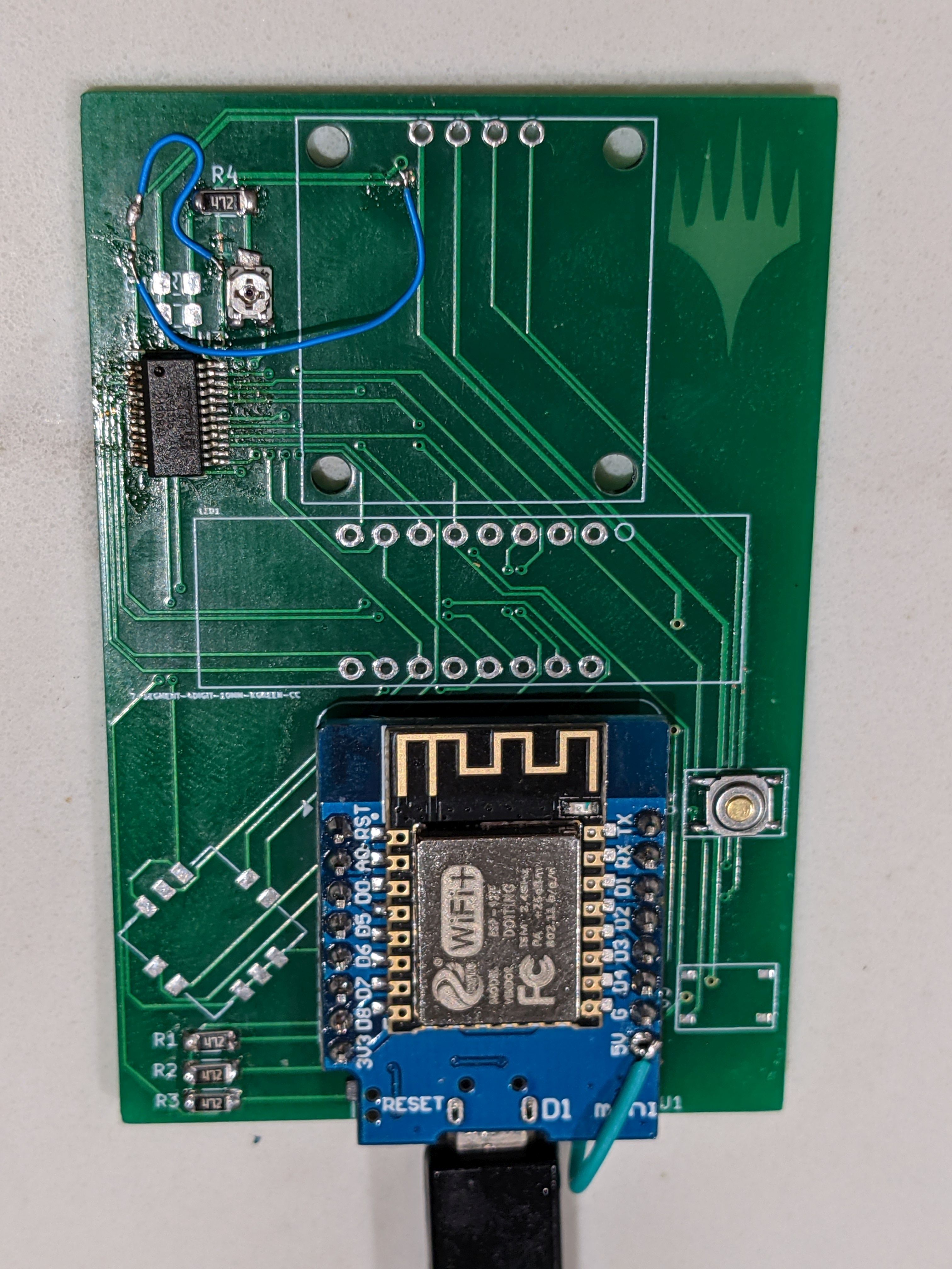
I actually did some follow up work on this. I really wanted to redeem myself for my dumb I2C pin mixup and get better buttons, so I made a second revision of the board. This revision accomplished all my todos, aside from adding an enclosure and battery.
Hardware
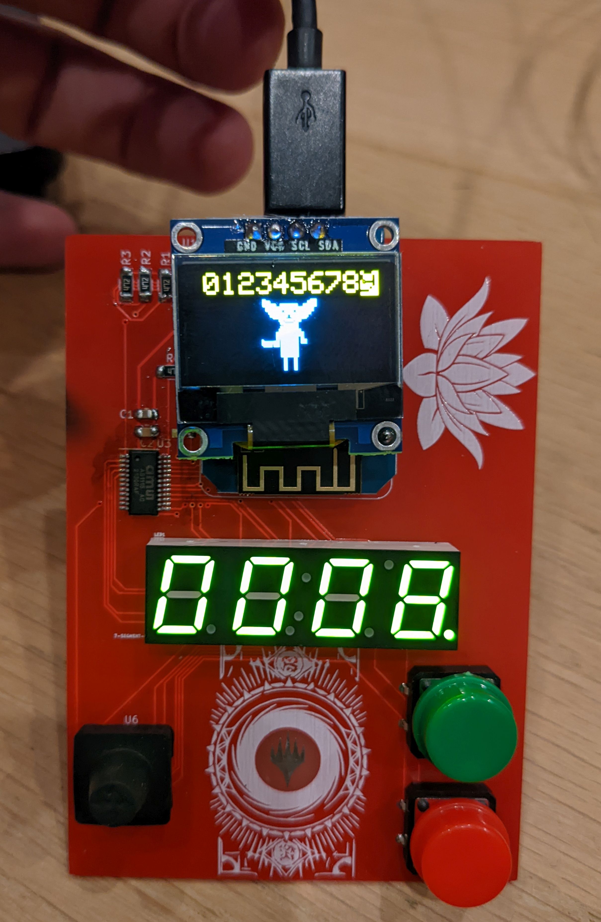
Due to chip shortages/streamlining the bill of materials, I swapped a couple parts. I had to switch the seven segment display with one that was pin compatible, and I switched the joystick to a pin compatible surface mount version from Amazon. Fortunately, it fit fine on my through hole footprints.
I still had a minor error in this revision where I made the holes for the buttons too small (now corrected in the design). I had to file down the pins a bit.
Since I hand assembled all five boards, I started coming up with a few additional refinements.
First, I improved my heat gun technique for attaching the AS1115. Here’s the process I ended up with:
- Tin the pads for the chip.
- Balance the board over the heat gun with the chip sitting on the pads.
- Heat the board from the bottom for 2 minutes on medium, then 2 minutes on high.
- Let the board cool.
- Test the connections and try to manually fix any shorts/missed connections with an iron. This ended up working reasonably well. I’d usually only need to clean up one or two pins.
I also evolved how I connected the OLED. I initially used stiff wires to connect the OLED to the D1 mini board. This worked well, but I was concerned it would put stress on the solder joints which might break over time. Subsequent boards I used spacers and hot glue to attach.
The last trick was to improve the joystick ergonomics. The bare joystick is a bit sharp. I had gotten some runner nubs, but I didn’t have a great way of attaching them, and didn’t have enough for all the boards. I found adding a dollop of hot glue and rotating the board to keep it in a ball made a ball topped stick like an arcade cabinet.
Software
See https://github.com/axlan/mtg-life-tracker/tree/master/firmware for firmware development.
With these fancy new boards, I also spend some time improving the software. I mostly focussed on creating a platform that could be easily configured, and could have a variety of mostly independent applications that I could switch between with a menu brought up by pressing down on the joystick:
I ended up with a high level design somewhat reminiscent of what I did for my wreath pixel clock way back when.
I created a base App class that would be the interface to each feature.
1
2
3
4
5
6
7
8
9
10
11
12
class App {
public:
  virtual void Up() = 0;
  virtual void Down() = 0;
  virtual void Left() = 0;
  virtual void Right() = 0;
  virtual void Increment() = 0;
  virtual void Decrement() = 0;
  virtual void Display() = 0;
  virtual const char* GetName() const = 0;
  virtual void Update() {};
};
The selected app has these functions called from the main run loop when it’s selected.
For configuration I started out with the WifiManager library. It seems to have undergone a recent refactor and was a bit buggy, so I made a fork to support the functionality I was interested in. I’d probably keep developing this going forward since this is a set of functionality I’ve wanted to add to a bunch of projects.